background image

18

Instruction book

Cancelling the drying phase

In case you do not want to wait until the drying phase is completed, you
can cancel it. 

1. Press in the On/Off button. The control lamp for the On/Off button 

goes out.

2. Open the door. The drying phase is cancelled. 

Setting the delay start

The programme start can be delayed by 3, 6 or 9 hours.

1. Press in the On/Off button.

2. Press the delay start button repeatedly, until the lamp next to the 

required hours of delay is lit.  

3. Press the button for the required programme. 

4. After the set delayed start time has elapsed, the programme starts.  

Reset the delayed start:
If the programme has not started, you can change the set time with the
delayed start button.

Cancelling the delayed start:
If the programme has not started, the delayed start can be cancelled. Press
the delay start button repeatedly, until none of the lamps next to the hours
are lit. The required programme starts immediately.

Switching the dishwasher off / unloading

Do not switch the dishwasher off until the indicator lamp        for the pro-
gramme cycle end is lit. 

1. Press in the On/Off button. The control lamp for the On/Off button 

goes out.

2. Leave the dishes in the dishwasher for approx. 15 minutes after 

the end of the programme so that they dry better and cool down.

3. Check the strainers/filters to see if they need to be cleaned when 

the dishwasher has finished the programme.

Hot dishes are sensitive to mechanical shocks. Always let the dis-
hes cool down before unloading.

english AEG Favorit CE  3-09-30 08.38  Sidan 18

Summary of Contents for Favorit CE

Page 1: ...Favorit CE Dishwasher Instruction book Aus Erfahrung Gut ...

Page 2: ...on of the appliance Next to this symbol you receive additional information and practical tips on using the appliance Tips and instructions for the economical and environmentally friendly use of the appliance are marked with a clover leaf In the event of a malfunction these operating instructions contain information on how to rectify faults yourself see the section In the event of a fault If these ...

Page 3: ...f the appliance 8 Prior to using for the first time 10 Programme chart 14 Loading the dishes 16 Using the appliance 17 Care and cleaning 19 In the event of a fault 20 Service 22 Service and spare parts 22 Position and connection instructions 23 27 Technical specifications 23 Installation 24 Information for test centres 27 ...

Page 4: ...d connect up your dishwasher please read the Installation section Before installing the appliance ensure that the nominal voltage and type of supply on the rating plate match that of the supply where the appliance is to be installed The fuse rating is also to be found on the rating plate Child safety Remember that the plastic bags included in the packaging can be fatal playthings for small childre...

Page 5: ...al AEG Service Force Centre Use only spare parts supplied by these If the mains lead is damaged or is to be replaced for a longer lead the cable obtainable from AEG Service Force must be replaced by a service engineer authorised by AEG Do not put any solvents in the dishwasher There is a risk of an explosion Do not sit or stand on the open door the appliance may tip over Before using special dishw...

Page 6: ...ructions were supplied PS stands for polystyrene moulded which is used for the sections of packaging needed to cushion the appliance The appliance contains plastic and rubber components These have identifying marks to show what they are made from so they can be recycled or disposed of properly at the end of the appliance s life cycle The materials are identified according to international standard...

Page 7: ...crystal glass pewter or copper items bonded cutlery items or dishes older cutlery with cement that is not temperature resistant cutlery with wooden horn china or mother of pearl handles For washing in the dishwasher the following are of limited suitability Only wash stoneware in the dishwasher if it is specifically marked as being dishwasher safe by the manufacturer Glazed patterns may fade if mac...

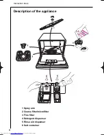
Page 8: ...8 Instruction book 4 5 1 Spray arm 2 Coarse filter microfilter 3 Fine filter 4 Detergent dispenser 5 Rinse aid dispenser 6 Salt container Description of the appliance ...

Page 9: ...and functions button In addition to selecting a programme you can press these two buttons to adjust the setting of the water softener Indicator lamps Shows Current phase of the selected programme Wash cycle in progress top lamp Drying in progress middle lamp Programme cycle ended lowest lamp Control lamps Shows that On Off button is pushed in Refilling of salt is necessary Refilling of the rinse a...

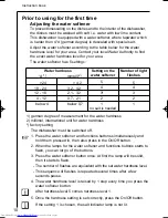
Page 10: ...rdness level is raised by 1 step every time you press the water softener button After hardness level 5 comes hardness level 1 5 Once the hardness setting is set correctly press the On Off button If the setting 1 is chosen the salt indicator lamp is not lit 1 german degree of measurement for the water hardness 2 millimol internationel unit for water hardness factory setting Prior to using for the f...

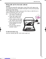
Page 11: ...lt please check each time that you really do have a packet of dishwasher salt in your hand 1 Unscrew the filler cap to the salt container anticlockwise 2 Fill the salt container with water only the first time 3 Fill the container with coarse salt using the funnel supplied 4 Remove the funnel and wipe off any spillage around the filler opening 5 Screw the filler cap back properly in place Fill with...

Page 12: ...locks again Fill with rinse aid When the indicator light on the control panel is lit If dishwasher detergent with rinse aid is used you can switch off the lamp that indicates that the rinse aid dispenser is empty The dishwasher must be switched off 1 Press the water softener and functions buttons simultaneously and hold them pressed in then also press in the On Off button 2 When the lamps for the ...

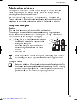
Page 13: ... wash water during the programme Please observe the manufacturer s dosing and storage recommenda tions as stated on the detergent packaging 1 Open the lid to the dispenser by pressing the lid catch towards the compartment 2 Filling with detergent Pre wash detergent is poured into the smaller compartment to the left when needed 3 Close the lid Avoid frequent use of liquid detergents as the long ter...

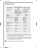
Page 14: ...arch All types of dishes NORMAL 65 Pre rinse Washing Rinse Final rinse Drying 92 minutes 13 minutes 0 80 kWh 7 litres normaly soiled dried on food remnants 1 Noise levels vary at different stages of the wash programme as at some programme stages the dishes are washed more energetically so that they will be cleaned more thoroughly 2 The consumption figures were determined under standard conditions ...

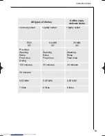
Page 15: ... rinse Washing Rinse Final rinse Drying 150 minutes 54 minutes 0 63 kWh 7 litres GLASS 50 Washing Rinse Final rinse 35 minutes 0 40 kWh 6 litres lightly soiled Coffee cups delicate items 30 MIN 40 Washing Rinse Final rinse 30 minutes 0 35 kWh 6 litres lightly soiled ...

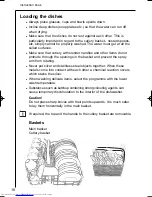
Page 16: ...gh the openings in the basket and prevent the spray arm from rotating Never put silver and stainless steel objects together When these metals come into contact with each other a chemical reaction occurs which stains the silver When washing delicate items select the programme with the lower wash temperature Substances such as ketchup containing strong colouring agents can cause temporary discoloura...

Page 17: ...oor carefully when the dishwasher is running since hot steam may escape Cancelling the programme 1 Press and hold in the button for the programme in progress until the indicator light for the programme goes out 2 Release the programme button The programme is now cancelled and a new programme can be selected If you switch the dishwasher off the selected programme is not finished it is only disrupte...

Page 18: ...d you can change the set time with the delayed start button Cancelling the delayed start If the programme has not started the delayed start can be cancelled Press the delay start button repeatedly until none of the lamps next to the hours are lit The required programme starts immediately Switching the dishwasher off unloading Do not switch the dishwasher off until the indicator lamp for the pro gr...

Page 19: ...e spray arm needs cleaning unscrew the nut anti clockwise remove the washer and lift off the spray arm Clear the holes and shake out any food remnants Coarse filter microfilter 2 The purpose of the coarse filter is to catch large objects such as tooth picks and pieces of eggshell Make sure that the filter is always clean Turn the coarse filter anti clockwise Lift it out and rinse it under running ...

Page 20: ... the water tap turned on Has your domestic water supply been cut off temporarily Is the water inlet hose kinked or blocked Is the filter inside the inlet hose blocked Is the water pressure too low Water not discharged at end of cycle Did you open the door before the pro gramme cycle finished Are the filters clogged Dishes not washed satis factorily Has anything prevented the spray arm from rotatin...

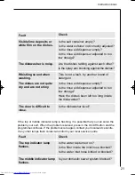
Page 21: ...ps flash contact and inform your local service centre Fault Visible lime deposits or white film on the dishes Check The dishwasher is noisy Are the dishes rattling against each other Is the spray arm knocking against the dishes Whistling sound when washing This is not a fault try another brand of detergent The dishes are not quite dry and are not shiny Is the rinse aid dispenser empty Is the rinse...

Page 22: ...out the need to call out an engineer If an engineer is called to resolve a problem listed below or to repair a fault caused by incorrect installation or mis use a charge will be made even if the appliance is under guarantee Give the appliance s model designation PNC number and F S Nr Serienumber according to the data plate affixed to the rear of the dishwasher You can record these details here Mod...

Page 23: ... the middle of the door Weight Net 22 kg Minimum Maximum Maximum 80 kPa 0 8 bar 1000 kPa 10 bar 65 C 230 V 50 Hz 10 A 1100 W 1180 W Electrical data Power supply Fuse Heating element Power rating This appliance complies with the following E E C directives 73 23 EEC dated 19 02 1973 low voltage directive 89 336 EEC dated 03 05 1989 incl amendment 92 31 EEC directive on electromagnetic compatibility ...

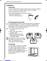
Page 24: ...f water which remains inside the parts of the dishwasher will freeze and damage it To prevent this you should 1 Turn off the water supply to the dishwasher 2 Remove the water inlet and discharge hoses 3 Make sure that there is coarse grained salt in the salt container for the water softener The appliance is only to be used and stored indoors at normal room tempe rature The manufacture is not respo...

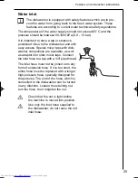
Page 25: ...asher connections are available as well as adaptors for older mixer taps Connect the inlet hose to a tap with a 3 4 pipe thread The inlet hose must not be joined onto any form of extension hose If it is too short the entire hose must be replaced with a longer high pressure hose specially designed for the purpose The end of the hose which is connected to the dishwasher can be turned in any directio...

Page 26: ...dishwasher must be connected electrically Place the discharge hose over the sink as illustrated It must not at any point be higher up than 75 cm over the surface which the dishwasher is standing on If it runs higher operation of the dish washer might be impaired It is also important to ensure that the inside diameter of the hose is not less than 13 mm at any point If the discharge hose is too long...

Page 27: ...the plug from the wall socket Test standard EN 50242 and EN 60704 Rated capacity 6 place settings accordance EN 50242 Loading of basket see chapter Loading the dishes Test program Eco 55 C Rinse aid Type III setting 3 Water pressure minimum 0 8 bar maximum 10 bar Waste water outlet install according to figure below Detergent IEC Type B 15 gram in the dispenser 3 gram in the pre wash dispenser Info...

Page 28: ...822 61 10 33 ...

Page 29: ...02 02 599 513 616 EN SERVICE MANUAL AEG Hausgeräte GmbH Muggenhofer Straße 135 D 90429 Nürnberg Germany Fax 49 0 911 323 1022 Spares Operation Publ Nr 599 513 616 06 03 02 EN Edition Dishwasher COMPACT MIDI DISHWASHER COMPACT MIDI ...

Page 30: ...me 10 6 Leakage Protection 11 Safety level 11 7 Water Inlet 12 8 Static filling 12 9 New pulse wash with random functionality 13 Circulation 13 Function of the new pulse wash with random functionality 13 10 Regeneration 14 11 Rinse out after regeneration 15 12 Pump out 15 13 In and Output elements 16 Position of pushbuttons LEDs and lamps 16 14 Overview of Service and After sales functions 17 15 O...

Page 31: ...ergie Water Super wash 70 C 1 15 kWh 9 l Normal 65 C 0 85 kWh 8 l Energy Saving 55 C 0 63 kWh 8 l Quickl 50 C 0 45 kWh 6 l Glass 40 C 0 39 kWh 6 l Installation water drainage Place the discharge hose over the sink as illustrated It may not at any point be higher then 75 cm over the surface which the dishwasher is standing on If runs higher operation of the dishwasher might be impaired It is also i...

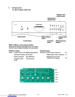
Page 32: ... 4 Spares Operation R Kurzke 02 02 599 513 616 EN 3 Components In and Output elements S 1 S 2 S 3 S 4 S 5 S 6 LD1 LD2 LD3 LD4 LD5 LD7 LD8 LD6 LD9 LD10 LD11 LD13 LD14 LD12 ...

Page 33: ... the water level Without water contact is opened fN Switch point with level 47 mm Ws Reset point with level 10 mm Ws Overfill 3 l The pressure switch is not adjustable Flow Heater The flow heater heats the water to the required temperature During the wash cycle water is contantly passing through the flow heater Power output 1100 W 1000 W UK Resistor 49 W 53 W UK Protector 98 C 5 K Thermal fuse 206...

Page 34: ...r output 23 W Pump rate 10l min NTC Temperaturfühler Temperature sensor NTC resistor Temperatur Widerstand 20 C 6032 Ω temperature resistor 25 C 4829 Ω nur bei vollelektron 30 C 3891 Ω Geschirrspüler 40 C 2573 Ω only for fully electronic dishw asher 50 C 1741 Ω 55 C 1444 Ω 60 C 1204 Ω 65 C 1009 Ω 70 C 849 Ω NTC Temperate sensor Electronic On electronic models a micro processor controls all compone...

Page 35: ... when the door is open Possibly existing rinse aid in compartments 2 and 3 flows back into the storage tank of the rinse aid The detergent trays are filled up The door will be closed and the detergent for prewashwillberinsedoutthroughtheslotsinthedetergent dispenser cover During the washing cycle the coil is switched on and the detergent compartment cover releases the detergent The rinse aid flows...

Page 36: ...e used up it is necessary to regenerate the softener This is done by flushing a brine solution through the softener Afterwards the softener is washed out with fresh water and is now fully effective Depending on the water hardness regeneration is only necessary after several wash cycles The softening system is designed for a water hardness of up to 35 dH With the coil switched off the rinse aid flo...

Page 37: ...hardness range The value is increased in w With setting WH1 no regeneration is usually carried out rotating manner No adding of salt is required B After pressing the key the key LED LD1 will Any salt LED available will not be activated go dark for about 3 seconds w Table of hardness range values C The new value is then displayed by coded flashing of LED LD1 Further sequence as described under 6 7 ...

Page 38: ... 10 Spares Operation R Kurzke 02 02 599 513 616 EN 4 Position of components ...

Page 39: ... 11 Spares Operation R Kurzke 02 02 599 513 616 EN 5 Water Course Scheme ...

Page 40: ... pressure monitor does not switch in this filling phase is generally limited electronically to 2 minutes If the pressure monitor has not switched in by then the electronics jump to the error mode shut off tap and the program is stopped If the pressure switch switches back during the cycle a maximum of 10 sec further filling is possible If the pressure monitor has not switched in by then the electr...

Page 41: ...generation dosage chambers and into softener The level control chamber built into the sump operates the pressure switch 8 Static filling Static filling until pressure switch point failure code If this point isnt reached after max 2 minutes a failure code is displayed and the program is stopped The program phase display PPD LED LD9 is blinking LD9 LD10 LD11 ...

Page 42: ...ycle definition Tr random time Tlow time for low speed Ratio factor for low speed eeprom definition 5 Circulation The circulation pump pumps the water simultaneously into the ceiling shower and into the spray arm The water is filtered in the sieves and led to the circulation pump Function of the new pulse wash with random functionality After the filling steps the circulation pump is running at two...

Page 43: ...KRXU IRU UHJHQHUDWLRQ YDOYH WH 1 4 dH 60 180 Sek WH 2 18 dH 16 180 Sek WH 3 26 dH 8 180 Sek WH 4 32 dH 5 180 Sek WH 5 50 dH 0 180 Sek This table is stored in EEProm Therefore the values are changeable by variant configuration The values on the left specify the actual status and shall only be seen as an example for this documentation Column Number water loads contains the value when the regeneratio...

Page 44: ... of the next wash pro gram Antisiphonic device If the end of the take off hose is below the level of the water in the wash space a siphon effect is possible that is the machine runs empty This is avoided by the ventilation through the anti siphon valve pump 30 sec 1 fill pump 8 sec pump 15 sec 2 fill pump 8 sec pump 15 sec 3 fill pump 8 sec pump 30 sec The pumping off stage usually takes about 50 ...

Page 45: ...2 LD3 blinking Í S1 Í LD1 blinking Í Delete Service failure memory Display test S2 S3 then afterwards S0 On Off Í LD1 LD2 LD3 blinking Í S3 Í 3 times short activation of all available LEDs with 2 sec Pause inbetween Í OO VHUYLFH DQG DIWHU VDOHV IXQFWLRQV FDQ RQO EH VWRSSHG E VZLWFKLQJ WKH PDFKLQH RI ZLWK WKH 2Q 2II VZLWFK 6 Except Water hardness adjust Function is also terminated by a 60sec timeou...

Page 46: ...ised although the circulation pump isn t activated Wrong variant programming no display no no not possible Checksum in EEProm not correct Only recognised after switching ON L D9 L D10 L D11 L D9 L D10 L D11 L D9 L D10 L D11 L D9 L D10 L D11 L D9 L D10 L D11 L D9 L D10 L D11 L D9 L D10 L D11 KDW KD SSHQV Progr LED blinking Program stopped After removing the failure the program can be continued bei ...

Page 47: ...7 60 14 10 10 s ec WHPSHUDWXUH 4 m in 65 C WLPH DIWHU WHPSHUDWXUH 5 5 5 5 5 5 5 5 ZDV K W SH ctrl pulse_2 pulse_2 pulse_2 pulse_2 pulse_2 pulse_2 pulse_2 pulse_2 WRWDO WL PH 6 8 6 6 6 WHPSHUDWXUH 4 m in 65 C WLPH DIWHU WHPSHUDWXUH 5 ZDV K W SH ctrl pulse_2 WRWDO WL PH 6 8 WHPSHUDWXUH 70 C 70 C 70 C 70 C 15 m in 68 C 65 C 65 C 9 m in 70 C 55 C 65 C WLPH DIWHU WHPSHUDWXUH T 1 T 1 T 1 T 1 T 1 T 1 T 1...

Page 48: ...ng o The duration of the program phase prewash is increased with this option by 18 20 minutes Changes in the cleaning phase o Additional 6 minutes of cleaning with heating to max 55 C o Additional 20 minutes cleaning with a controlled temperature of 70 C resp 65 o The duration of the program phase cleaning is increased with this option by approx 26 minutes This option doesn t influence the program...

Page 49: ...imited to 10 seconds o Exceeding this limit causes a failure code display and the program cycle is stopped PPD LED LD9 is blinking measure to cleaner and rinse aid The activation times of the dispenser were optimised with the EDW1000 o In program phase cleaning 30 seconds ON o In program phase hot rinse 30 seconds ON 30 seconds OFF 30 seconds ON The dosage of rinse aid is temperature controlled at...

Page 50: ...ront of the door Before finally opening unclip the on off LED The electronics can then be snapped out You need screwdriver Torx TX20 The dosing unit is held by screws After removing these screws the components can be removed from the door breech Re assembly is carried out in the reverse order After removing the spring the door opener can be removed from its hinges ...

Page 51: ...ved from its hinges together with the deflection band After removing the screws on the chassis and on the door frame the door hinge can be removed Housing After removing the housing screws lay the machine on its side from the bottom of the machine the housing is unclipped front and back from the catches and can be removed ...

Page 52: ...lation can be unscrewed for cleaning when necessary in case these rubber parts in the interior of this valve become dirty or stuck because of residues The pressure monitor is simply unscrewed The air should be able to enter the hose from the hol der not the other way around ...

Page 53: ... the bosses for the overflow water and the flooding switch After removal you come to the most important functional components After loosening the screws of the two holders and the yoke the circulation pump pump continuous flow heater unit can be taken out The bayonet breech of the pump impeller housing can be simply released for possible cleaning ...

Page 54: ...mps it is recommended that this assembly be taken off its hinges After the removal of the hose the valve can be drawn out of the chassis with suitable pliers The mounting for the thermostats is screwed in behind the drain pump After its release the thermostats can be removed ...

Page 55: ...lamps are released and the screws removed The flooding switch is snapped out with a small screwdriver and can be taken out of its mounting After removing the protective cap the microswitch can be snapped out Here you can see how the hose clamps can be re tensioned with wire cutting pliers ...

Page 56: ... The connections on the reed switch are removed The hose connections are detached The large nut of the salt hol der can be released with the help of a V belt A spanner is useful in removing the recycling inlet nut Now the complete unit can be removed After undoing the screws of the recycling valve this can be removed ...

Page 57: ... 29 Spares Operation R Kurzke 02 02 599 513 616 EN ...

Page 58: ... 30 Spares Operation R Kurzke 02 02 599 513 616 EN ...

Page 59: ...and values Reed switch salt 0 W empty Heater 49 W 53 W UK Reed switch rinse aid 0 W empty NTC temperature sensor 5 25 kW room temperature tacho generator circulationspumpe 223 W coil dispenser unit 1 35 kW door switch 0 W regeneration valve 4 5 kW inlet valve 3 8 kW pressure switch no level 0 W with level circulation pump Main coil 126 W drain pump 200 W 4 7 ...

Page 60: ...N9113380102_1 ...

Page 61: ...N9113380102_2 ...

Page 62: ...empty Heater 49 W 53 W UK Reed switch rinse aid 0 W empty NTC temperature sensor 5 25 kW room temperature tacho generator circulationspumpe 223 W coil dispenser unit 1 35 kW door switch 0 W regeneration valve 4 5 kW inlet valve 3 8 kW pressure switch no level 0 W with level circulation pump Main coil 126 W drain pump 200 W 4 7 N9113380102_3 ...

Page 63: ... in 65 C WLPH DIWHU WHPSHUDWXUH 5 5 5 5 5 5 5 5 ZDV K W SH ctrl pulse_2 pulse_2 pulse_2 pulse_2 pulse_2 pulse_2 pulse_2 pulse_2 WRWDO WL PH 6 8 6 6 6 WHPSHUDWXUH 4 m in 65 C WLPH DIWHU WHPSHUDWXUH 5 ZDV K W SH ctrl pulse_2 WRWDO WL PH 6 8 WHPSHUDWXUH 70 C 70 C 70 C 70 C 15 m in 68 C 65 C 65 C 9 m in 70 C 55 C 65 C WLPH DIWHU WHPSHUDWXUH T 1 T 1 T 1 T 1 T 1 T 1 T 1 T 1 T 1 ZDV K W SH pulse_2 pulse_...

Page 64: ...ht Width Depth mm mm mm 490 595 580 Carboran 6 Cupshelf Grey 50 1100 10 Other docum Product no Brand Market Design fam Type Approval Programmes Inlet hose Outlet hose Electr cord 3 4 Programmes Replaces Hook outlet h Climb hose x Noise level IEC 704 3 dB Freestanding Built in A Intensive 70 Normal 65 Energy saving 55 Quick 50 Glass 40 x x x x x 53 49 Electronic Push button On Off Delayd start x x ...

Page 65: ...s and with the same position The configuration of this board is possible only if you have the suitable equipment software and hardware for this type of activity and if you have taken part to the training It is still not possible to programme the not configured electronic boards in all Countries ATTENTION We will not accept returns of not configured electronic boards that have been wrongly ordered ...

Page 66: ...e part catalogues of the affected models have been updated when the production started PART NOS For all the models a specific Kit part no 5027 82 60 00 0 is supplied and consists of Denomination No pcs Part no Detergent dispense with adapter included 1 111 57 50 40 6 Faston 2 5024 12 55 00 4 Faston cover 2 5022 59 95 00 5 Fitting Instructions 1 9914 16 12 89 7 Notes for interchangeability The new ...

Page 67: ...salt rinse aid sensor to the new adapter supplied in the kit g Connect the adapter to the detergent dispenser use if necessary a clamp to gather all the cables together h Remount the external door ATTENTION ATTENTION The particular fastons and faston covers supplied with the kit must be especially used on the I TRONIC dishwasher series as the detergent dispenser part no 152 08 06 40 5 and 152 08 0...

Page 68: ...lső ajtók Pótalkatrész száma Mosogatógép típus 5024 10 82 00 2 Gyártmány SOLARO 45cm es típus 1987 tól máig 5024 10 83 00 0 Gyártmány SOLARO 60 cm es típus 1980 tól máig 5024 10 84 00 8 Gyártmány NÜRNBERG 60 cm es 1 típusú FAVORIT 1984 tól 1995 ig Megjegyzés a belső ajtón egy dombornyomott A látható 5024 12 70 00 3 Gyártmány NÜRNBERG 60 cm es 2 típus 1995 tól máig Megjegyzés a belső ajtón egy domb...

Page 69: ...ystem We have introduced a new Coarse strainer micro filter 150954401 9 to prevent clogging of the drainsystem 150954401 9 shall replace the 150954400 1 version in all service visits Product ser no ELC The new version was introduced in the production week 4 2003 The old 150954400 1 version is fitted to all MIDI 911 338 0 911 339 0 since the prod start week 15 2002 new old from below from above ...

Page 70: ...lektronok hirtelen az egyik tárgyból a másikba áramolnak Az ESD károsodás bármikor megtörténhet Az ESD károsodás a teljes munkafolyamat elektronikus kezelése során felmerülhet Termékbeérkezés Gyártás Összeszerelés Raktározás Csomagolóanyag Szállítás Ügyfélszolgálat ESD a területi ügyfélszolgálaton A területi szervizmunkánál felmerülhet az ESD érzékeny eszközök mint például háztartási készülékeink ...

Page 71: ... lehető legkisebb mértékben érintse Az áramköri kártyát helyezze földelt felületre és soha ne érintse meg a MOS áramkört Ahol az áramköri modulokkal programozási célból kell dolgozni statikus disszipatív szegélyt és kézelőt kell csatlakoztatni a földpotenciálhoz A készüléken belül való kártyabeszerelés és programozás során a szervizmérnöknek földelnie kell magát Az ESD t megelőző szabályok betartá...

Page 72: ...eg a PCB t még mindig a készüléken 2 Ezután helyezze az USB csatlakozót a számítógépbe 3 Majd csatlakoztassa az USB t az interfészeszközhöz 4 A programozási fázis során ne érintse meg a PCB t PCB áramellátás MEGJEGYZÉS A földelés számára piacon szintén elérhetőek a mobil ESD szervizfelszerelések és az európai dugaszolócsatlakozók A 405506395 4 alkatrészszám elérhető a Distripartsnál mint ESD szerv...

Page 73: ...ere the float switch has been activated by water in the base tray This could be caused the lock nut under the salt cap being very loose It is very important on any service calls made to the compact dishwasher that the locknut is checked to ensure it is fully tightened It should not be possible to unscrew by hand If the lock nut requires to be tightened care should be taken not to fracture the nut ...

Page 74: ...sok fülei a fából készült vágódeszkáknak és eszközöknek a korábban leírt okok miatt nincs elég nagy tömegük hogy energiát halmozzanak fel hő formájában és alacsony a hővezető képességük Ezért természetes hogy a szárítás végén vízcseppek maradnak ezeken az edényeken 3 A teflon serpenyők magának az anyagnak a hatásánál fogva tovább megtartják a vizet a teflon bevonat egyfajta korlátként működik alac...

Page 75: ... só fényesítő A tabletták hatékonysága nagy mértékben csökken 25 30 F feletti vízkeménység esetén A jobb szárítási teljesítmény elérése érdekében erősen ajánlott a fényesítő adagolás használata akkor is ha tablettát használnak 10 MINDIG ellenőrizze az üstben levő víz keménységét az 1 töltettel Abban az esetben ha az a 3 5 D tartományon kívül esik ellenőrizze a keménységet a csapnál és állítsa be a...

Page 76: ...Explosionszeichnungs Nr N 8731 A06 Number of picture ...

Page 77: ...Explosionszeichnungs Nr N 8731 A07 Number of picture ...

Page 78: ...Explosionszeichnungs Nr N 8731 A08 Number of picture ...

Page 79: ...Explosionszeichnungs Nr N 8731 A09 Number of picture ...

Page 80: ...Explosionszeichnungs Nr N 59112003232 Number of picture ...

Page 81: ...r make sure that the anchors are back in their original position f Connect the cables for the salt rinse aid sensor to the new adapter supplied in the kit g Connect the adapter to the detergent dispenser use if necessary a clamp to gather all the cables together ATTENTION The particular fastons and faston covers supplied with the kit must be especially used on the I TRONIC dishwasher series as the...

Reviews: