background image

24

24

ADDITIONAL BATTERY SAFETY WARNINGS


WARNING! 

To reduce the risk of fire, personal injury, and 

product damage due to a short circuit, never immerse the tool, 
battery pack, or charger in fluid or allow fluid to flow inside them. 
Corrosive or conductive fluids, such as seawater, certain industrial 
chemicals, and bleach or bleach-containing products, etc., can cause 
a short circuit.

ACTIVE KICKBACK AND OVERLOAD DISPLAY

The kickback feature is active when the dotted blue lights are 

on. When the product detects tough soil or debris, the feature is 

activated to protect the user. When the product stops, release the 

trigger and then remove the product from the hole.
The overload function is activated when the red bar light is 

highlighted. When the product stops, release the trigger and then 

remove the product from the hole.

SWITCH POSITION

Display

Description

Location

REV

Reverse

Bottom

1

Speed 1

Middle

2

Speed 2

Top

NOTE: 

Turning  off  the  kickback  prrotection  at  any  time  is  not 

recommended. However, in the event that it is deactivated, the 

product still has overload protection.

Ensure that the operator has a firm grip and solid stance when using 

the product.

TRANSPORTATION AND STORAGE


Turn off the product, remove the battery pack, and allow the 
product to cool down before storing or transporting.


Clean all foreign material from the product.


Do not store or transport the product with the battery pack 
fitted. Remove the battery pack, and secure it separately. Store 
the product in a cool, dry, and well-ventilated place that is 
inaccessible to children. Keep the product away from corrosive 
agents, such as garden chemicals and de-icing salts. Do not 
store the product outdoors.


For transportation in vehicles, secure the product against 
movement or falling to prevent injury to persons or damage to 
the product.

TRANSPORTING LITHIUM BATTERIES

Transport the battery pack in accordance with local and national 

provisions and regulations.
Follow all special requirements on packaging and labelling when 

transporting batteries by a third party. Ensure that no batteries can 

come in contact with other batteries or conductive materials while 

in transport by protecting exposed connectors with insulating, non-

conductive caps or tape. Do not transport batteries that are cracked 

or leaking. Check with the forwarding company for further advice

MAINTENANCE


Use only original manufacturer’s replacement parts, accessories, 
and attachments. Failure to do so can cause possible injury, can 
contribute to poor performance, and may void your warranty.


Servicing requires extreme care and knowledge and should 
be performed only by a qualified service technician. Have the 
product serviced by an authorised service centre only. 

 WARNING! 

The auger bit is very sharp. To prevent personal 

injury, exercise extreme caution when cleaning, fitting, or removing 
the auger bit. Always wear protective gloves when performing 
maintenance on the bit.


Turn off the product and remove the battery pack before 
conducting any maintenance or cleaning work.


You may make adjustments and repairs described in this 
manual. For other repairs, contact an authorised service centre.


After each use, clean the body and handles of the product with 
a soft, dry cloth. Any part that is damaged should be properly 
repaired or replaced by an authorised service centre.


Check all nuts, bolts, and screws before each use and at frequent 
intervals for proper tightness to ensure that the product is in 
safe working condition. Any part that is damaged should be 
properly repaired or replaced by an authorised service centre.


Bring the product to an authorised service centre to replace 
damaged or unreadable labels.

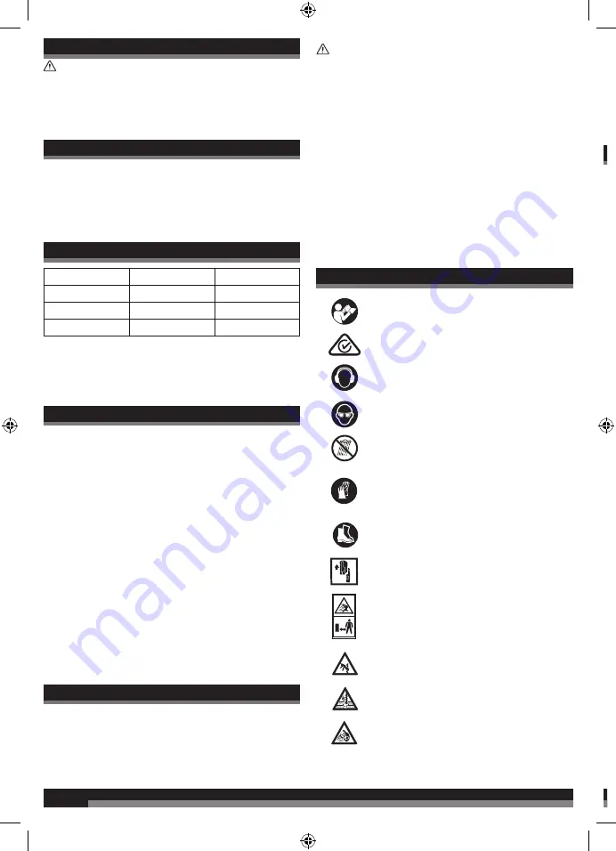
SYMBOLS ON THE PRODUCT

Read and understand all instructions before 

operating the product. Follow all warnings and 

safety instructions.

Regulatory Compliance Mark (RCM). Product 

meets applicable regulatory requirements.

Wear ear protection.

Wear eye protection.

Do not expose the product to rain or damp 

condition.

Wear non-slip, heavy-duty protective gloves.

Wear non-slip safety footwear when using the 

product.

Remove the battery pack before starting any work 

on the product.

Beware of thrown or flying objects. Keep all 

bystanders, especially children and pets, at least 15 

m away from the operating area.

Keep feet and legs away from the auger.

Never operate the auger in areas with underground 

electric, gas, water, or telephone lines.

Maintain a firm grip with both hands on the auger 

during operation.

89

Guaranteed sound power level

Waste electrical products should not be disposed 

of with household waste. Please recycle where 

facilities exist. Check with your local authority or 

retailer for recycling advice.

SYMBOLS IN THIS MANUAL

Note

Warning

.

Summary of Contents for FUSION A18FPHD142

Page 1: ...ALT58LI401 ALT58B ADT18 A18FPHD142 ...

Page 2: ...ual before assembling operating and maintaining the product Subject to technical modifications WARNING To prevent personal injury or damage to underground utility equipment consult local organisations for advice such as DIAL BEFORE YOU DIG call 1100 or visit www 1100 com au ...

Page 3: ...3 3 ADT18 x 1 x 1 x 1 x 1 x 16 x 8 x 8 x 1 x 1 x 1 ...

Page 4: ...4 4 LE St St Sp FW A18FPHD142 x 2 x 2 x 1 x 1 x 1 x 1 x 1 x 1 x 1 x 16 x 8 x 8 ...

Page 5: ...vated Release the trigger and turn on the product again to continue digging If the kickback protection is continuously activated lower the auger speed or clear the auger from the hole more often Speed mode LED Solid green Indicates what speed the auger is spinning at Speed 1 100 rpm Speed 2 150 rpm Speed 3 200 rpm FWD REV LED Solid green Indicates which direction the auger is spinning in TRIGGER R...

Page 6: ...6 6 START STOP 13 14 STARTING THE PRODUCT OPERATING THE PRODUCT 12 INSTALLING THE HANDLE ASSEMBLIES INSTALLING THE BATTERIES 8 ...

Page 7: ...7 7 19 17 11 16 10 STORING THE PRODUCT CLEANING THE PRODUCT INSTALLING THE AUGER INSTALLING THE KICKBACK BAR USING THE KICKBACK BAR ...

Page 8: ...he powerhead slide in the left hand handle assembly and align the bolts holes handle without the trigger switch 3 Facing the LED side of the powerhead slide in the right hand handle assembly and align the bolt holes 4 Insert the bolts through the frame holes with a washer on either side of the frame Install and hand tighten nuts on each bolt to keep the handles in place 5 6 7 ...

Page 9: ...cable in the right handle assembly to the signal cable from the powerhead Ensure that the pins are aligned before connecting and securing 7 Connect the signal cable in the right handle assembly to the signal cable from the powerhead Ensure that the pins are aligned before connecting and securing ...

Page 10: ...10 10 IN 1 2 3 INSTALLING THE KICKBACK BAR NOT on t com ...

Page 11: ...11 11 1 2 3 4 click INSTALLING THE AUGER NOTE When attaching the auger align the holes on the drive shaft and auger This is most easily completed by laying the product on the ground ...

Page 12: ...12 12 1 2 click 1 2 INSTALLING THE BATTERIES NOTE The product requires two battery packs to operate For best performance use two FORCE battery packs of the same capacity ...

Page 13: ...13 13 START STOP STARTING THE PRODUCT ...

Page 14: ... 14 click 1 2 OPERATING THE PRODUCT NOTE Always use the product with 2 hands Keep the product as close to the body as possible to prevent injury and ensure kickback protection can be activated if required ...

Page 15: ... speeds 100 150 200 RPM The multiple speeds can be beneficial in different scenarios In rocky soil a slower speed may help in preventing kickback issues NOTE Frequently remove dirt and debris from the hole and auger during use to improve digging efficiency ...

Page 16: ...16 16 STOP USING THE KICKBACK BAR NOTE If the kickback protection is activated release trigger allow the kickback bar to go back to its natural position and then restart the product to continue digging ...

Page 17: ...17 17 3 4 2 1 CLEANING THE PRODUCT ...

Page 18: ... auger can be cleaned with water once it has been removed from the powerhead and moved away to a safe distance from the powerhead NOTE Do not clean the powerhead with water Only clean it with a dry cloth or soft brush ST ...

Page 19: ...19 19 3 4 2 1 STORING THE PRODUCT ...

Page 20: ...20 20 6 5 NOTE Always store the product in a cool dry well ventilated area BA Co INT The hav man The area by a TE Vo RP We We Au Ma Vi Vi No A Un A Un WA The acco of e The app sign An run Iden acce ...

Page 21: ... Voltage 36V d c 2 x 18 V RPM Speed 3 200 10 min Speed 2 150 10 min Speed 1 100 10 min Weight with battery pack no auger 10 5 kg Weight with auger and two battery packs 15 05 kg Auger size 250 mm Maximum reach 600 mm Vibration level in accordance with AS NZS 62841 1 2015 A1 2015 Vibration Left handle 0 858 m s2 K 1 5 m s2 Right handle 1 022 m s2 K 1 5 m s2 Noise emission level in accordance with A...

Page 22: ...thing and gloves away from moving parts Loose clothes jewellery or long hair can be caught in moving parts SER AD If devices are provided for the connection of dust extraction and collection facilities ensure these are connected and properly used Use of dust collection can reduce dust related hazards Do not let familiarity gained from frequent use of tools allow you to become complacent and ignore...

Page 23: ...y damaged parts before use Do not modify the product in any way or use parts and accessories which are not recommended by the manufacturer Do not allow familiarity with the product to make you careless A careless fraction of a second is sufficient to inflict serious injury Keep handles and grasping surfaces dry clean and free from oil and grease Slippery handles and grasping surfaces do not allow ...

Page 24: ...ials while in transport by protecting exposed connectors with insulating non conductive caps or tape Do not transport batteries that are cracked or leaking Check with the forwarding company for further advice MAINTENANCE Use only original manufacturer s replacement parts accessories and attachments Failure to do so can cause possible injury can contribute to poor performance and may void your warr...

Page 25: ... uct mp he ork all 15 nd ger 89 Guaranteed sound power level Waste electrical products should not be disposed of with household waste Please recycle where facilities exist Check with your local authority or retailer for recycling advice SYMBOLS IN THIS MANUAL Note Warning ...

Page 26: ......

Page 27: ...t under our control By referencing or displaying the third party we do not in any way represent that we recommend or endorse the relevant third party its goods or its services We do not accept any responsibility in connection with any third party If you engage with any such third party features we will not be liable under any circumstance for your engagement and you do so entirely at your own risk...

Page 28: ...1 Gilby Road Mount Waverley VIC 3149 Australia Techtronic Industries N Z Limited Unit C 70 Business Parade South Highbrook Auckland 2013 New Zealand www aegpowertools com au www aegpowertools co nz AEG is a registered trade mark used under license from AB Electrolux publ 2020 21 Techtronic Cordless GP 960087599 01 ...

Reviews: