background image

1.

3

1.3-02

2/4!Ҿጎ

ၭ႐ǖඓԍ܏ୟഗतഄ޹ॲڦ๑ᆩݔྷփגࡗኸۨܮۨኵă

ӭሏࡗײዐ܏ୟഗփీᇑॕᆘ՗௬ಸጐă

փڥሞॕᆘई֢ٚ՗௬ฉཱྀጅईࣂۯ܏ୟഗă

ॽยԢҾጎሞ߅ሳĂ࿮פĂ࿮ޫ์Ⴀڦ࣍ৣዐă࣍ৣཉॲ

ՂႷޙࢇ!JFD!71:58!ᄲ൱ࢅ0ईԨ๮֩ዐࡀۨڦཉॲă

සࡕยԢݣዃሞփޙࢇԨ๮֩ࡀۨཉॲڦ࣍ৣዐLj൩૴ဣ

ፌৎڦၨ๳ևோă

ഔހ܏ୟഗ

ഔހኮമLjഽଜॺᅱॠֱሏ๼णጎၒLjऻ୤ሏ๼ईӭሏࡗ

ײዐ؜၄ڦ໦࣋ጒ઄ăස݀၄ยԢ๴໦Lj൩૴ဣሏ๼ฆLj

ሞت૙ኮമ༵ࠃ۩ڇࡽĂሏ๼ຕ਍ࢅ໯ᆶ၎࠲႑တă

..!঴ਸ઒ሾټLjၭ႐ൽူԈጎၒ0ྂಎฉ߃ă

..!ൽူഄ໱Ԉጎ֌ଙࢅ၎࠲࿔ॲă

..! ቴڟժൽ؜Ҿጎࢅ֡ፕ๮֩ăԍ٪๮֩ᅜՍࢫ೺๑ᆩ

ࢅ֖ለăॠֱ๮֩๟ޏ๟໯ႴڦᇕჾӲԨăසࡕփ๟Lj൩

૴ဣፌৎڦၨ๳ևோă

..! ॠֱԈጎၒా๟ޏᆶ޹ॲĂ૶থۈӱࢅഄ໱ᆘॲڪగ

ၵ൧઄ူ࿄Ҿጎڦፇॲă

..! ยԢཚ׉๑ᆩஅພࠦۨሞԈጎၒ0ྂಎڹևă຿ਸժൽ

ူኄၵஅພLjॽ܏ୟഗٗԈጎၒ0ྂಎዐൽ؜ă

BREAKER

܏ୟഗ

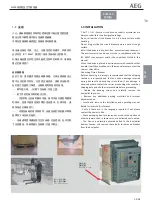
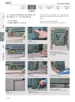
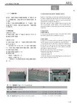
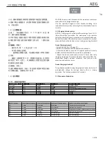
1.3 INSTALLATION

C AU T I O N : Ensure circuit brea ke randits accessories are 
always used within their designated ra

Ɵ

ngs.

Do not allow the circuit breaker to hit a hard surface while 
handling.
Do not drag or slide the circuit breaker across a hard or rough 
surface.
Install the device in a dry, dust-free, noncorrosive environment. 
The environmental condi

Ɵ

ons must be in compliance with the 

IEC 60947 requirements and/or the condi

Ɵ

ons stated in this 

manual.
When the device is placed in environments with condi

Ɵ

ons that 

deviate from those men

Ɵ

oned in this manual please contact the 

nearest  sales o

ĸ

ce.

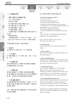
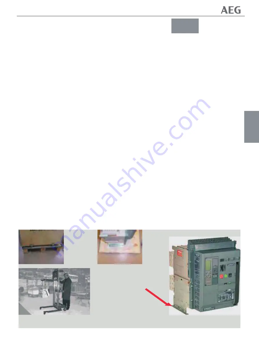
Unpacking Circuit Breaker
Before unpacking it is strongly recommended that the shipping 
container is inspected and that any undue damage incurred 
during transport and handling is recorded. If any damage is 
observed please contact the carrier men

Ɵ

oning order number, 

shipping data and all other relevant data before proceeding.
-- Unbind the banding straps and carefully remove the 
box/pallet top cover.
-- Remove any addi

Ɵ

onal packing materials and relevant 

documenta

Ɵ

on.

-- Locate and remove the installa

Ɵ

on and opera

Ɵ

ng manual. 

Retain for later use & reference
. Verify if these are in the language required. If not please 
contact the nearest o

ĸ

ce.

-- Check packaging box for accessories as connec

Ɵ

on pads and 

other hardware that , in some cases, are delivered unmounted.
-- The Device is normally delivered bolted to the box/pallet 
bo

Ʃ

om. Loosen and remove these bolts to removed breaker 

from the box/pallet.

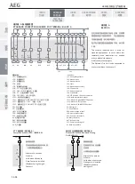
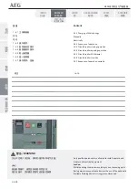
Ҿጎ

Ҿጎ࿋ዃ

Ҿጎ࿋ዃ

0 RXQWLQJORFDWLRQ

ǖ༵ื๮כ

ǖ༵ื๮כ

)LJ/LIWLQJ7UXFN

NF1:ဣଚگუ੣ഘ܏ୟഗ

Summary of Contents for ME09

Page 1: ...ME09 空气断路器 5000 6400A 用户手册 ...

Page 2: ...WKRRGF YKVJ VJG CRRTQRTKCVG EQXGTU CPF QT DG KPUVCNNGF KP C UWKVCDNG GPENQUWTG QT RCPGN VCMKPI VJG TGSWKTGF UCHGV ENGCTCPEGU KPVQ CEEQWPV 0QP QORNKCPEG YKVJ VJGUG TGSWKTGOGPVU EQWNF TGUWNV KP FCOCIG VQ RTQRGTV CPF QT UGXGTG KPLWT VQ RGTUQPPGN Caution Important Requirements য়ߢ ๖ ణ Ԩ ዐ ๖ ڦ ยԢሞሏႜ क़ॽ থ ሞླ၃ ߛڦ უ ۉ ᇸă ୟഗ ਸߛ ୁۉ Ljᆮഄ ୟ ୁۉ Lj ీׂࣷิߛ ጱࣅഘ ă ৈሎႹࢇ ටᇵӀቷ Ҿඇᄲ ҾጎĂۙ ĂྼႪई߀ጎԨยԢă ୟഗՂႷದԢҾጎሞࢇ ڦ त ݴ ୯କ Ҿඇक़ဤ...

Page 3: ...cƟons may result in product damage NOTICE An aid meant to assist the user in performing the set task Please retain for future use This documen is based on informaƟon availableat the Ɵme of its publicaƟon While eīor ts have been made to ensure accuracy the informaƟon contained herein does not cover all details or variaƟons in hardware and soŌware nor does it provide for every possible conƟngency in...

Page 4: ...5 Tools Needed for InstallaƟon 1 2 PRODUCT SPECIFICATIONS Tables 1 3 INSTALLATION 1 3 1 LiŌing and MounƟng LiŌing Truck and Adapter 1 3 2 Fixed PaƩern Circuit Breaker InstallaƟon 1 3 3 Drawout PaƩern Circuit Breaker InstallaƟon Removal from CasseƩe MounƟng in CasseƩe 1 3 4 Secondary Disconnect Terminal Blocks LocaƟon Use Table General schemaƟcs Table DeĮniƟon of connected devices to Block A and Bl...

Page 5: ...r to breaker Interlock 1 of 2 breaker interlock 1 of 3 breaker interlock 2 of 3 breaker interlock 2 of 3 breaker interlock with priority 3 4 Network Interlock 4 0 ACCESSORIES DESCRIPTION General InformaƟon 4 1 Releases Coils 4 2 Electrical Charging Motor 4 3 Contacts 4 4 InstallaƟon parts 4 5 Accessories 4 6 Spare parts 5 0 MAINTENANCE TESTING AND TROUBLESHOOTING 5 1 Maintenance InspecƟon Schedule...

Page 6: ...Serial Number Measurement Units 1 1 1 Short Product DescripƟon 1 1 2 Features and CharacterisƟcs 1 1 3 Storage 1 1 4 RaƟng label descripƟon 1 1 5 Tools Needed for InstallaƟon Fig 1 0 5000A 6400A Front View A Accessory Indicator B Charging Handle C Electrical ON Close D Manual ON Close E Closing Spring Discharge BuƩon F ON OFF PushbuƩon Status G ON OFF Status Indicator H Spring Charge Status I Brea...

Page 7: ...luded in the circuit breaker casseƩe and trip unit if ordered Catalogue number descripƟon see Appendix Product Serial Number When communicaƟng with AEG on any aspects of this device please menƟon the serial number Each circuit breaker has a unique serial number located in two places On the top face of one of the retractable liŌing brackets On the leŌ side viewed from front of the front cover 1 1 1...

Page 8: ...eases ST are conƟnuous rated Undervoltage releases have a built in Ɵme delay of up to 50 ms an external Ɵme delay module is available if longer Ɵme delays are required TDM Both closing coils are equipped with an anƟ pumping mechanism OpƟonal status indicaƟon contacts are available for the ST CC and UVR coils They can be wired out through the trip unit communicaƟon opƟon or through the secondary di...

Page 9: ...uxiliary Contacts Power rated 8NO 8NC Interlocks Standard Interlocking Feature Drawout Breaker The casseƩes and device mobile part are equipped with a interlock that prevents the breaker from closing unless it is in the TEST or CONNECTED posiƟon The device also opens the main breaker contacts before the mobile part leaves and or approaches the CONNECTED posiƟon When the main breaker contacts are c...

Page 10: ...n the casseƩe euchenon and can be used for locking the shuƩers in closed posiƟon and or closing and locking the racking handle aperture The third opƟon is located on the breaker drawout support slides and can be used to lock breaker chassis combinaƟon in disconnected posiƟon Facia PushbuƩon Padlocking FaciliƟes To prevent un authorized access to both the ON and OFF push buƩons on the breakers fron...

Page 11: ...two parts a factory mounted interlocking mechanisms and two or more separately available cables Bell Alarm Contact A changeover contact that once ĮƩed to the breaker indicates if the breakers has tripped on one of it s protecƟve funcƟons Electronic Trip Unit An interface on the Trip Unit front face allows a Manual or AutomaƟc breakers reset The Bell Alarm Contact will only permanently change posiƟ...

Page 12: ...equired Hand Tools 2 2ǖՂႴ ڦ ਏఁ 0ࠀీ ಇഭ HVOJ ǖ ᆩᇀൽူಇ๕ ۅة ႜॠֱă அີ ژ DŽ9 nn ᅃጴ๕Džǖ ᆩᇀገ ۯ ཉऐࠓ ڔ ӱ ۯد ጎዃă ాୃঙӮ 6 nn ǖ ᆩᇀָႂ ࢷቸ ႜॠֱࢅྼࢺăᆩᇀָႂ ईۙবࠦۨ๕ࢅᅎ ۯ ๕ ࢷ ۅة ă ాୃঙӮ 5 nn ǖ ᆩᇀָႂ ۉ ऐ ፕഗҾጎஅۤă ࠅ ဤࡀǖ ᆯᇀॠֱ ࢷ ۅة क़ဤă அີ ژ ॲ ǖ ᆩᇀָႂऐႁࢅ ۉ ጱፇॲҾጎஅۤăᆩᇀॽ ದ থ ޤڟ ዺ ۅة থ ă அີ ژ ॲ ǖ ᆩᇀָႂമ௬ӱҾጎஅۤă Tool Name FuncƟon Cluster pliers GUNI To remove cluster contacts for inspecƟon Screwdriver 8 mm Ňat To operate racking aperture shuƩ...

Page 13: ...0 VWS3 ཚ ۉ MQ21ǖ ۉ ഘ ං ۨ MQ22ǖ ୟഗ ᇀ EJTDPOOFDUFE DŽ ਸDž ዃ MQ23ǖ ୟഗ ᇀ UFTUDŽ Dž ዃ MQ24ǖ ୟഗ ᇀ DPOOFDUFE DŽ থDž ዃ DDǖԿࢇ ං TUǖ ݴ ੩ഗ VWSǖവ ۉ უ ੩ഗ TQSǖ ీئࣟڑ ጒༀ SUDǖጚԢԿࢇጒༀ Nǖ ۯۉ ऐ ፕഗ CBUǖয়ଯԒয়ཌቄ DDDǖཚრԿࢇ ං OJǖ ۉ ഘ ං CC Closing coil ST Shunt release UVR Undervoltage release SPR Spring charge status RTC Ready to close status M Motor operator BAT Bell alarm trip CCC Command closing coil NI Network Interlock Indica...

Page 14: ... 26ǖऐࠓණኤ Tool Name FuncƟon Table 1 2 Environmental CondiƟons Table 1 6 IEC 60947 AC DC Version Performance CharacterisƟcs Table 1 7 IEC 60947 AC DC Version Rated Endurance SpeciĮcaƟons Table 1 9 Non AutomaƟc CB Switch IEC Version Table 1 10 Non AutomaƟc CB Switch Endurance SpeciĮcaƟons Table 1 11 ConnecƟon opƟons for breaker in Įxed paƩern Table 1 12 ConnecƟon opƟons for breaker in draw out paƩern...

Page 15: ... 20 000 ْ ۯۉ ऐ ፕഗĂവ ۉ უ ੩ഗ 12 500 ْ ॲ 12 500 ْ 2 3 ׂ ࡀ ඓԍৈᆯࢇ ڦ ටᇵҾጎĂ ፕĂྼႪࢅྼࢺ ᆶ ۉ ഘยԢă 2 3ǖ ৣཉॲ0Ubcmf 2 3 Fowjsponfoubm Dpoejujpot Ensure only qualiĮed personnel install operate service and maintain all electrical equipment Accessories AlƟtude AlƟtude CorrecƟon factors Ambient surrounding circuit breaker appendix F Change of Temperature CharacterisƟc ClimaƟc Closing Coil Cold Current In Damp Heat D...

Page 16: ...ࢇ ୁۉ Jdn ୟఱ ీ Jdx lB ڇ ፇ ๕ ࠓ ޏ ࢇᆩፕ ഗ 7ǖ ࢇޙ JFD 71 58 3 ڦ Ⴀీ ट ీ ݴ Jdv lB Air Circuit Breaker DenominaƟon Category of use Envelope type HIOSC release set at Isolator Making Current Release set at nr of poles in series Number of PosiƟve ON OFF Power Circuit Breaker type Rated current In Rated impulse withstand voltage Uimp Rated insulaƟon voltage Ui Rated operaƟonal voltage Ue Service breaking capac...

Page 17: ...ps 75 2 8ǖ ࢇޙ JFD 71 58 2 ڦ ఱ Ⴀ ഘ ୟഗఁ Կࢇ0 ਸ ፕ ۉ ഘఱ Ⴀ ॐ ڪ प ᆶ ୁᆌᆩዐ ڦ ఱ ႠLj൩ ለ JFD 71 58ă ऐႁఱ Ⴀ ഘ ୟഗ႙ࡽ ୁۉۨܮ Jo 8ǖ ࢇޙ JFD 71 58 ڦ ఱ Ⴀ ྼࢺཉॲူ փྼࢺཉॲူ Air Circuit Breaker DenominaƟon CO operaƟons Electrical Endurance Envelope type For Endurance in DC applicaƟons please refer to the IEC 60947 Mechanical Endurance Power Circuit Breaker type Rated current In With Maintenance Without Maintenance English ० ዐ ࡀ...

Page 18: ...n 1 3 3 Drawout PaƩern Circuit Breaker InstallaƟon Removal from CasseƩe MounƟng in CasseƩe 1 3 4 Secondary Disconnect Terminal Blocks LocaƟon Use Table General schemaƟcs Table DeĮniƟon of connected devices to Block A and Block B NF1 ဣଚ گ უ ഘ ୟഗ ణ ጀ opuf য়ߢ0WARNING ඓԍৈᆯࢇ ڦ ටᇵҾጎĂ ፕĂྼႪࢅྼࢺ ᆶ ۉ ഘยԢă ඓԍ ืยԢీࠕ ت Ⴔᄲ ื ڦ ยԢă ٻح Ҿඇ ஷĂ ࢅҾඇၸă Ensure only qualiĮed personnel install operate service and maintain...

Page 19: ... in this manual When the device is placed in environments with condiƟons that deviate from those menƟoned in this manual please contact the nearest sales oĸce Unpacking Circuit Breaker Before unpacking it is strongly recommended that the shipping container is inspected and that any undue damage incurred during transport and handling is recorded If any damage is observed please contact the carrier ...

Page 20: ...Ɵon on a suitable support structure using four M8 bolts torque to 25 N m 3 A clearly marked grounding point is provided on either side of the circuit breaker 1 3 3 Drawout Circuit Breaker InstallaƟon Drawout type circuit breakers are normallydelivered already mounted in casseƩes 1 Remove the circuit breaker from its casseƩe using withdrawal procedures described in SecƟon 1 4 2 PosiƟon the casseƩe ...

Page 21: ...g 1 5 2 Fully extend the casseƩe draw out support slides unƟl they reach a posiƟve stop 3 Lower the device on to the drawout support slides making use of the liŌing methods described here Carefully verify that the rollers ĮƩed to the mobile part of this device are correctly engaged on the slides Įg 1 6 4 Push the circuit breaker into the casseƩe unƟl it reaches a posiƟve stop The circuit breaker i...

Page 22: ...ă 8 ൽူժ ݣ ᄩ դă 9 ୟഗُ ጚԢ ჃLj ᅜኟ ሏႜ ᇀ DPOOFDUFEDŽ থDž ዃ ڦ ᄩ դ Sbdljoh esjwf jo DPOOFDUFE qptjujpo ᇀ UFTUDŽ Dž ዃ ڦ ᄩ դ Sbdljoh esjwf jo UFTU qptjujpo ᄩ դ ݣ ዃ Sbdljoh Iboemf Tupsbhf Mpdbujpo ᇀ EJTDPOOFDUFEDŽ ਸDž ዃ ڦ ᄩ դ Sbdljoh esjwf jo EJTDPOOFDUFE qptjujpo ჽฦ ڦ ᄩ դ Sbdljoh Iboemf Fyufoefew ॽยԢٗ ॐዐઙ ᅜՍൽူă Qvmmjoh efwjdf gspn dbttfuuf gps sfnpwbm ᄩ դ ڔ ӱ ۯد ጎዃ ዃ Sbdljoh Iboemf Tivuufs esjwf mpdbujpo ᄩ դౚࢇLjਸ๔...

Page 23: ...omaƟcally added In cases where the accessories are mounted in the Įeld Ordering details GSDFTR2 408030 For devices in a Įxed paƩern a full set of terminal blocks with 78 connecƟons Block A B is available as a spare GSDWT 408053 For devices in a drawout paƩern an addiƟonal terminal block with 39 connecƟon points is available as a spare BLOCK B The terminals can be used up to a raƟng of 6A at 440V A...

Page 24: ...4 CC C5 D1 UVR D2 1 A26 A14 A15 A16 A17 A18 A19 A20 A21 A22 A23 A24 A25 31 32 21 22 11 12 33 34 23 24 13 14 A27 A28 A29 A30 A31 A32 A33 A34 A35 A36 A37 A39 A38 TU 97 98 TU 07 08 96 98 95 N N B1 B2 B3 B4 B5 B6 B7 B8 B9 B10 B11 B12 B13 ST1 17 18 81 82 UVR 1 27 28 71 72 TU 61 62 51 52 41 42 B27 B28 B29 B30 B39 B31 B32 B33 B34 B35 B36 B37 B38 ZSI ZSI TxEN1 Rx Tx Ucom U1 U2 U3 B26 B17 B18 B19 B20 B21 B...

Page 25: ...ups ీئࣟڑ ጒༀ ۅة tqsjoh dibshf tubuvt dpoubdut ڼ ᅃ ݴ ੩ഗ ۉڦ ᇸ qpxfs joqvu up gjstu Tivou sfmfbtf ڼ ᅃ വ ۉ უ ੩ഗ ۉڦ ᇸ qpxfs joqvu up gjstu Voefswpmubhf sfmfbtf d4ǖԿࢇ ංଭ d5 6ǖԿࢇ ංआ d4 dmptjoh dpjm ofvusbm xjsf d5 6 dmptjoh dpjm qibtf xjsf ޤ ዺ Կ ۅة bvyjmjbsz OD dpoubdu ޤ ዺ ਸ ۅة bvyjmjbsz OP dpoubdu ๑ᆩ opu jo vtf ۉ ጱ ੩ഗ ڦ ी ۉ ഗ sfmbz pvuqvu gspn usjq voju ۉ ጱ ੩ഗ ޤڦ ዺ ۉ ᇸ bvyjmjbsz qpxfs tvqqmz up usjq voju...

Page 26: ...MQ ǖTU3 ཚ ۉ 0 VWS3 ཚ ۉ MQ21ǖ ۉ ഘ ං ۨ MQ22ǖ ୟഗ ᇀ EJTDPOOFDUFEDŽ ਸDž ዃ MQ23ǖ ୟഗ ᇀ UFTUDŽ Dž ዃ MQ24ǖ ୟഗ ᇀ DPOOFDUFEDŽ থDž ዃ DDǖԿࢇ ං TUǖ ݴ ੩ഗ VWSǖവ ۉ უ ੩ഗ TQSǖ ీئࣟڑ ጒༀ SUDǖጚԢԿࢇጒༀ Nǖ ۯۉ ऐ ፕഗ CBUǖয়ଯԒয়ཌቄ DDDǖంସԿࢇ ං OJǖ ۉ ഘ IndicaƟon LP1 Spring charge status LP2 Breaker open LP3 Breaker closed LP4 Fault LP5 Breaker ready to close LP6 CC powered LP7 UVR not powered LP8 ST powered LP9 ST2 powered UVR2 not powered...

Page 27: ...OOFDUJPO TDIFNF GPS UFSNJOBM CMPDL C ॐ ዃኸ๖ ۅة থ DPOOFDUJPO TDIFNF gps Dbttfuuf Qptjujpo Joejdbujpo Dpoubdut ڦ ੩ഗኸ๖ ۅة থ DŽ ጱӱ CDž pqujpobm Dpoofdujpo Tdifnf Sfmfbtf Joejdbujpo Dpoubdut CMPDL C ኸۨยԢฉ๑ᆩ ੩ഗኸ๖ ة ۅ ᆶၳă DŽ پ 4 ޤ ዺ ۅة Dž Alternate ConnecƟon Scheme Valid when Release IndicaƟon Contacts are used on the indicated devices Replaces 3 Aux Contacts ᆩࢽኸۨ ۉڦ ୟǗኸ๖ഗ MQ22ǖ ୟഗ ᇀ ਸ ዃ MQ23ǖ ୟഗ ᇀ ዃ MQ24ǖ ୟഗ...

Page 28: ...losing operaƟon 1 4 4 Circuit breaker opening operaƟon 1 4 5 Circuit breaker Withdrawal 1 4 6 Circuit breaker InserƟon 1 4 7 Sequence of operaƟon casseƩe ణ ጀ opuf য়ߢ0WARNING ৈሎႹࢇ ටᇵҾጎĂ ፕࢅྼࢺ ᆶ ۉ ഘยԢă ၭ႐ǖ ӭሏ ୟഗ LjՆ௨ᅺᅎ ۯ ևॲܸ ฅă ྼࢺยԢ Ljഽଜॺᅱ๑ᆩ ڦ থ ں ጎዃă Only qualiĮed personnel are allowed to install operate and maintain all electrical equipment CauƟon Whilst handling the breaker avoid injury due to movin...

Page 29: ...ecƟon Allow the handle to return to it s original posiƟon A clearly audible click indicates that the operaƟon is completed Repeat the above menƟoned process 10 Ɵmes thus fully charging the springs The status indicator will now be RED The mechanism design includes measures that prevent over extension and operator injury Device Charging electrical The opƟonally available spring charging mechanism mo...

Page 30: ...et buƩon is not protruding from the front cover The circuit breaker is not posiƟoned anywhere between CONNECTED TEST and DISCONNECTED If any of the above condiƟons are NOT met the device is prevented from closing 2 Closing the Device Up to four diīerent ways A D of closing the breaker are available A Manual Closing Depressing the ON pushbuƩon located on the breaker front facia Fig 1 0D page 1 4 B ...

Page 31: ...inals Undervoltage release Undervoltage releases can be installed and will open the breaker once their power supply drops below a certain level AddiƟonally mulƟple in and external breaker interlocking faciliƟes are available that if present and acƟve will open the device 1 4 5 Circuit Breaker Withdrawal PreparaƟon Neutral Pole Current Transformer When using a ground leg current transformer supplie...

Page 32: ...DISCONNECTED posiƟons NOTICE When the racking handle is inserted in the racking shaŌ the circuit breaker cannot be operated in any posiƟon between CONNECTED and DISCONNECTED Removing the handle automaƟcally resets the racking handle shuƩer 5 From the DISCONNECTED posiƟon conƟnue turning the racking handle anƟ clockwise unƟl reaching a posiƟve stop NOTICE Ensure that the closing springs are fully d...

Page 33: ... DISCONNECTED WITHDRAWN engaged disengaged disengaged disengaged disengaged disengaged engaged engaged closed closed closed open circuit breaker may be operated both mechanically or electrically ready for service circuit breaker may be operated both mechanically or electrically circuit breaker and control circuit operaƟons may be tested and veriĮed circuit breaker may be operated only mechanically...

Page 34: ...n Scheme CONTENT ጀ note য়ߢ0য়ߢ0WARNING փኟඓ تڦ ඓԍӀቷ ᆶ ᆩ ࡀڦ ሶኟඓ ت ۉ ă য়ߢǖ ৈሎႹࢇ ටᇵҾጎĂ ፕࢅྼࢺ ᆶ ۉ ഘยԢă ၭ႐ ӭሏ ୟഗ LjՆ௨ᅺᅎ ۯ ևॲܸ ฅă IMPROPER DISPOSAL Ensure baƩery is properly disposed ofaccording to all applicable regulaƟons WARNING Only qualiĮed personnel are allowed to install operate and maintain all electrical equipment CauƟon Whilst handling the breaker avoid injury due tomoving parts ୟഗ ॲ BREAKER LOCKS...

Page 35: ...rrent seƫng Current raƟng of Breaker LT or overload Current seƫng ST or Timed Short circuit Current seƫng Long Time or Overload protecƟon LT or overload Ɵme delay band Making Current Release Reduced Instantaneous Short Time or Timed Short circuit Current seƫng STDB ST or short circuit Ɵme delay band x Ie MulƟple of Primary Breaker seƫng Ie x In MulƟple of Breaker Current raƟng x LT MulƟple of LT o...

Page 36: ... EVENTS informaƟon is accessed through these Įve keys UP Scroll up or increment value DOWN Scroll down or decrement value RIGHT Next funcƟon or next page LEFT Previous funcƟon or previous page ENTER Save or set in to memory 2 1 3 Electrical Requirements None Plug in installaƟon Done on de energized units 2 1 4 Equipment Interfaces ME09 5000 6400ACircuit Breakers Trip units for the most part do not...

Page 37: ...bove the Mpro type N Trip Units also can receive inputs from external voltage condiƟoners All Trip Units can be opƟonally supplied by a 24 VDC control power supply Note external 24 VDC control power is required for communicaƟon All trip unit types have a connecƟon to an auxiliary switch within the breaker that senses the breaker s posiƟon 2 1 4 1 COMMUNICATIONS External 24 VDC control power is req...

Page 38: ...pro Electronic Trip Units type S and N The breaker reset mode can be chosen by a selector switch on the Trip Unit front as indicated in Įgure 2 3 There are 2 possible posiƟons or conĮguraƟons 1 manual In this conĮguraƟon the assembly in the trip unit interlocks with a mechanical lockout funcƟonality of the circuit breaker When the circuit breaker trips a mechanical interlock changes state This Int...

Page 39: ...ยዃDž Կ ీႠ ስႠኴႜ ࠦۨ ڦ ຨ ई ITJPD ԍࢺ Jj ยዃ ྺྷݔ 2 6 ڟ 26 y JfDŽᅃْยዃDž օ ྺ 1 6DŽࠌ 3 ยዃDž Կ ీႠ ᇺ ࢅײ Ԩ ں PODŽഔ ۯ Džࢅ PGGDŽ ԿDžLjਏᆶ ዃኸ๖႑ࡽă ยዃ ྺྷݔ 1 2 ڟ 2 y JoDŽ ୟഗ ۨܮ ኵDž 2 օ ྺ 1 12DŽࠌ 3 ยዃDž Կ ీႠ 25 Ԡჽ ยዃ HGEC Lj ྺྷݔ 61 ڟ 951 ࡹ ă25 Ԡჽ ยዃ HGEC Lj ྷݔ ྺ61 ڟ 951 ࡹ ă ਸ क़ ࢇޙ JFD 51 8 2 ࢅ JFD 71475 ᆩ 3 J3 u ԍࢺ क़ ྷݔ ᆩ 2 භີ J5 u ԍࢺ क़ ྷݔ ᇆᇱሶ ۉ ᇸথ ݓں ᇱሶ ీ ڦ VFGĂSFG ࢅ TFG ᆌᆩ ీ ڦ VFGĂSFG ࢅ TFG ᆌᆩፇࢇ ୁۉ DŽM2ĂM3ĂM4ĂODž ۉ უDŽM2ĂM3ĂM4Dž ํाጺీଉ...

Page 40: ...eps of 0 5 A total of 29 seƫngs Possibility to Switch OFF Remote and Local ON and OFF with posiƟon indicaƟon signal Seƫng RANGE from 0 1 to 1 x In Breaker RaƟng 1 Steps of 0 01 A total of 92 seƫngs Possibility to Switch OFF 14 Time delay seƫngs GFDB ranging from 50 to 840 milliseconds delay seƫng resulƟng in a 110 to 900 Milliseconds Clearing Ɵme Clearance Ɵmes to IEC 40979 1 and IEC 60364 2 I2 t ...

Page 41: ...ot the front cover of the raƟng plug or the plug may be damaged GENERAL BATTERY INFORMATION The trip unit has a front panel mounted baƩery When the baƩery is present the user can view data on the LCD and read or program the trip unit via the keypads The baƩery allows the user to display data change set points and provide thermal memory The baƩery does not allow normal trip unit operaƟon i e over c...

Page 42: ...trip unit or viewing trip targets when the breaker is de energized and external control power is unavailable All normal setup meter and status funcƟons can be performed with baƩery power ీࠀ ۉ Ԣጀ BATTERY FUNCTION Žƌ ƚĞŵƉĞƌĂƚƵƌĞƐ ĂďŽǀĞ ϰϬ ĂŶLJ ŬĞLJ ŵĂLJ ŚĂǀĞ ƚŽ ďĞ ŚĞůĚ down for up to 5 sec for the trip unit to be powered Remark Replace the baƩery if it does not power up the trip unit when any key is pr...

Page 43: ... and the save icon appears on the top of the LCD This indicates that the value has been stored in memory and is acƟve 5 ConĮrm seƫngs on the trip unit aŌer making changes by exiƟng and re entering SETUP mode and rechecking each changed seƫng 2 2 ፕ 2 2 1 ፕఇ๕ 2 2 2 SETUPDŽยዃDžఇ๕ Nqsp ۉ ጱ ੩ഗᆶ 5 ዖ ፕఇ๕ǖยዃĂᅏ Ăጒༀ ࢅ ॲă ᅜ๑ᆩ ۉ ጱ ੩ഗኟ௬ฉ ڦ 6 Ӏ ႜ ፕă VQDŽၠฉDžǖၠฉࡐ ۯ ईሺेຕኵă EPXODŽၠူDžǖၠူࡐ ۯ ई३ၭຕኵă SJHIUDŽၠᆸDžǖူᅃࠀీईူᅃᄻă MF...

Page 44: ...otecƟon seƫng Ir 2 2 3 1 1 Long Time Delay On overload ProtecƟon LTD 2 2 3 2 Short Time Pickup Delayed Short Circuit ProtecƟon ST 2 2 3 1 1 ჽ DŽࡗሜԍࢺDžLTD 2 2 3 2 ๔ ୁۉۯ DŽჽ ୟԍࢺDžST 2 3ǖ ۨ ڦ LTD ྷݔ ዐኸۨࡗሜ ڪ पူࡗሜཌቄ क़DŽ ڇ ྺ Dž Ҿጎሞ ᆶૌ႙ ۉڦ ጱ ੩ഗዐLj ڼ ᅃ TFUVQDŽยዃDž ఇ๕၂๖๔ዕ Mpoh Ujnf QjdlvqDŽ क़๔ ୁۉۯ Dž ยዃ ۅ ă ᅜሞ ยዃ ۅ ยۨ ୟഗ ୁۉۨܮ Jsă ᆩࢽ ᅜሞ ڼ ᅃ ၂๖ೡฉፌ ܠ ยۨ 7 փ ཞ ڦ ᆩࢽ ۉ ୁ JfLj ยዃྺ ݴ ๕ 2Ă1 9Ă 1 8Ă1 7Ă1 56 ई 1 5 y ୟഗ ۨܮୁۉ ኵ Jo...

Page 45: ...ჽ ጲ ૬Lj ᅜ ስăၽ ยዃԈઔ 4 I u ၽ DŽ2Ă3Ă4Džࢅ 2 ࠦۨჽ ăࠦۨჽ ྷݔ ᆶ 28 ۨ क़ ྷݔ ă ፌ ࢅ ፌ ჽ क़ሞ 3 6 ዐଚ ă ၽ ࢅࠦۨჽ ྷݔڦ ሞԨᆌᆩ 7 2ዐࣼ ྺ क़ ୁۉ ă ҾጎሞNqsp T ࢅ Nqsp O ႙ ۉ ጱ ੩ഗዐLj ڼ ෙ TFUVQDŽยዃDžఇ๕၂๖ೡྺ ۙব ڦ ስႠຨ ࡗ ୁۉ ԍࢺă ڟٳ ۨ ୁۉڦ प Jj ࢅ ڦړ հႚᄲ Lj ጎዃ ࣷ ة ுᆶჽ ڦ ୟഗཌቄă๔ ୁۉۯ ኵ ᅜยዃྺ օ 1 6 y ยዃ ڦ ᆩࢽ ୁۉ ኵ JfLj ྺྷݔ 3 1 y Jf ڟ 26 y JfăDŽ7511B ႙ጎዃฉፌ ྺٷ 24 y JfDž ຨ ๔ ୁۉۯ ඓ ྺ 21 ăNqsp T ࢅ Nqsp O႙ ۉ ጱ ੩ഗਏᆶᆩࢽ ᅜ ስ ڦ ገ ຨ ࡗ ୁۉ Lj े ڦ PGGDŽ ਸDžኵ ၄ሞຕኵଚ ă ስ ย ዃ ᆩ...

Page 46: ... pickup is acƟvated at the Ɵme the circuit breaker closes and for six cycles thereaŌer When the six cycles are over the threshold changes to the HSIOC pickup seƫng 2 2 3 3 1 ߛยዃຨ ԍࢺ HSIOC 2 2 3 3 1 High Set Instantaneous ProtecƟon HSIOC ITJPD ᄺ ࡗྺ ሜ๔ ۯ ԍࢺăNF1 ୟഗዐ๑ᆩ ۉڦ ጱ ੩ഗದᆶࡗሜຨ ཌቄԍࢺǖ ۙব ስႠຨ ԍࢺยዃྺ PODŽഔ ۯ Dž LjITJPD ยዃኵཚ ยዃྺ ୟഗ Jdx ۨܮ ኵ ڦ 218 ă සࡕ ۙব ስႠຨ ԍࢺยዃྺ PGGDŽ ԿDžLj ITJPD Ք ๔ ୁۉۯ ই ୟഗ Jdx ڦ 9 Lj ୯ ࠅ...

Page 47: ...seƫng range of 0 1 to 0 2 becomes available 2 Timings in Red meet the requirements of the IEC 60479 1 and IEC60364 standards at a frequency of 50 cycles 2 2 3 6 1 থ ࠤں ቱჽ GFDB The GT E GT S GT N Trip Units can opƟonally be equipped with a ground fault protecƟon that operates on a residual principle GFsum The device uƟlizes the internal Rogowski sensors in the circuit breaker to measure and to resi...

Page 48: ...ed to be coordinated with one or more mains or incoming breakers the use of a interconnecƟon device or mulƟplier is strongly recommended The AEG TIM device Catalogue number TIM1 can be used for these kind of applicaƟons This device also requires a 24VDC control voltage power supply When a ZSI input is received an upstream breaker will not use the standard ST ZSI and or GF ZSI delay band and slope ...

Page 49: ...he ME09 circuit breaker The Trip Units are fully compliant with Modbus Protocol Full details of the Modbus protocol can be found in the Modbus Protocol SpeciĮcaƟon Two wire Modbus 485 are supported The link Host may operate at a 300 600 1200 2400 4800 9600 or 19200 baud rate An overview of the communicaƟon parameters and register is included in SecƟon 2 5 of this manual Table 2 9 Input Input Assig...

Page 50: ...g neutral protecƟon and the value thereof depends on the network and installaƟon conĮguraƟon The following opƟons are available Neutral unprotected 0 Neutral protected and the LT protecƟon set at one of three values 50 Half Neutral protecƟon 63 Neutral ProtecƟon 100 Full Neutral protecƟon Seƫng the LT device in the Neutral pole inŇuences other installed protecƟon devices if present as indicated in...

Page 51: ... ዐႠԍࢺ PT CONN PT VOLTAGE PT ۉ უ ยዃන ยዃ क़ ᇕჾ ஓ MODBUS ں ST ZSI ST ZSI ST ZSI GF ZSI GF ZSI GF ZSI ी ۉ ഗ 1 ी ۉ ഗ2 1 ๔ ୁۉۯ 0 2 x CT ݔ ྷ 1Ljၽ Կ OFF OFF OFF 0 50 63 100 PH PH 120 19200 Y 0 M0 D 0 h ᆈ 0 1 ๔ ୁۉۯ 1 5 x LT ݔ ྷ 1Ljၽ Կ ๔ ୁۉۯ 1 5 x LT ݔ ྷ 1Ljၽ Կ ๔ ୁۉۯ 1 5 x LT ݔ ྷ 1Ljၽ Կ ๔ ୁۉۯ 0 2 x CT ݔ ྷ 1Ljၽ Կ ๔ ୁۉۯ 0 2 x CT ݔ ྷ 1Ljၽ Կ ๔ ୁۉۯ 0 2 x CT ݔ ྷ 1 ၽ Կ 1 ፇ 1 ፇ OFF 0 OFF OFF OFF 1 5 OFF PH PH 120 19200 0 ...

Page 52: ...osen value save chosen value save chosen value save chosen value save chosen value save chosen value save chosen value save chosen value save chosen value save chosen value save chosen value save chosen value save chosen value save chosen value save chosen value save chosen value A GF SUM RELT ZONE SEL INTLK INPUT 2 NEUTRAL PROTECTION PT CONN PT VOLTAGE MODBUS BAUDRATE SET DATE SET TIME LANGUAGE P...

Page 53: ...must use V L N and for a Delta construcƟon type V L L PotenƟal Transformers are available as ME09 accessories and are mounted and connected externally Note Energy reset is supported from setup soŌware and over communicaƟons Nqsp T ႙ ۉ ጱ ੩ഗ๔ዕದᆶҾಢ Ljᆩᇀ ଉࢅኸ๖ M2ĂM3 ࢅ M4 ᅜतዐႠटዐ ୁۉڦ ă Nqsp O ႙ ۉ ጱ ੩ഗದᆶ ଉ ຕ ڇڦ ᇮLj ຕࢅ ڇ ස 3 23 ๖ăᄲ ݡ ᆶᇑ ۉ უ ڦ ຕLj ۉ ጱ ੩ ഗՂႷದԢ ۉ უ႑ࡽLj๑ᆩྔև ڇ ट ۉ უࢻߌഗăՂႷ ስኄၵጎዃժߵ ۉ ᇸ ኙDŽZ ႚईෙঙႚDžॽጎዃ ...

Page 54: ... N 0 A L1 N 1 V L2 N 0 V L3 N 0 V L1 L2 2 V L2 L3 1 V L1 L3 0 V PHA 0 kW PHB 0 kW PHC 0 kW TOTAL 0 kW PHA 0 kW PHB 0 kW PHC 0 kW ݓ METER DŽᅏ Dž ၂๖ೡ SETUP METER STATUS EVENTS CURRENT APPR PWR APPR PWR PWR DMD ENERGY FREQUENCY PWR FACTOR PWR FACTOR CURRENT VOLTAGE VOLTAGE REAL PWR REAL PWR REAL PWR PHA L1 0 A PHB L2 0 A PHC L3 0 A PHA 2 kVA PHB 1 kVA PHC 0 kVA TOTAL 1 kVA PRST 3 kW PEAK 2 kW TOTAL 0 k...

Page 55: ...cƟon 5 The Circuit Breaker or Device status ON OFF Trip status Version status SoŌware version build date CommunicaƟon status Baud Rate Parity 2 3 3 STATUS mode ၠฉ ၠᆸDŽူᅃ Dž ၠူ ၠፑDŽฉᅃ Dž ඓණ DŽԍ Dž Ӏ Up Right Next Down Left Previous KEY Enter Save ย ዃ ᅏ ጒༀ ॲ ยዃጒༀ ๔ ۯ ጒༀ ٱ ဃጒༀ ୟഗጒༀ ཌቄጒༀ ӲԨ ཚ႑ยዃ PU DLY ୟഗ ਸ ๔ ۯ E 01 Կࢇ ਸ ް ཌቄ ॲӲԨǖ ิׂන ǖ հ ǖ ആ ၯᄓǖ ݓ METER DŽᅏ Dž ၂๖ೡ METER SETUP STATUS EVENTS SETTING STATUS PIC...

Page 56: ... trips Shunt trip OpƟonal if the coil contact is used Under voltage Release trip OpƟonal if the coil contact is used BIM Trip Unit Mismatch Breaker Interface Module The following informaƟon is stored with each event RMS currents Phase Type of trip Trip counter Time and date stamps Trips are logged under self power without Ɵme stamp Events with Ɵme stamps are only logged when 24VDC control power is...

Page 57: ...ཌቄ 3 TFUVQ ยዃ 0 VOEFS WPMUBHF വ ۉ უ 3 TFUVQ ยዃ 0 voefswpmubhf വ ۉ უ 3 TFUVQ ยዃ 0 WPMUBHF VOCBM ۉ უփೝ 3 TFUVQ ยዃ 0 XBWFGPSN DBQUVSF հႚ վइ 3 TFUVQ ยዃ 0 XZF 3 TFUVQ ยዃ 0 y DU 3 TFUVQ ยዃ 0 y Jo 3 TFUVQ ยዃ 0 y MU 3 TFUVQ ยዃ 0 Z 3 TFUVQ ยዃ 0 FSP USJQ ଭཌቄ 3 TFUVQ ยዃ 0 POF TFM JOUML ᇘ ስ 3 TFUVQ ยዃ 0 TJ TU 4 NFUFS ᅏ 0 bdujwf qpxfs ᆶࠀࠀ 4 NFUFS ᅏ 0 bqqbsfou qpxfs ࠀ 4 NFUFS ᅏ 0 BQQS QXS ࠀ 4 NFUFS ᅏ 0 dvssfou ...

Page 58: ...r a combinaƟon of two breakers Please contact your local AEG Sales Oĸce for more informaƟon Time Current Curve Breaker In 5000A LT ProtecƟon device Set at Ie 5000A Ir at 0 9 4500A Band C 10 ST ProtecƟon device Set at 6x Ir of 4500A Ist 27000 Band STDB 10 I ProtecƟon Device Set at 12 x Ie of 5000 Ii 60000 GF ProtecƟon device Set at 0 6 x Ie of 5000 Ig 3000 Band GFDB 6 I t ON M d Green Light Blue Li...

Page 59: ...0 300 8N2 7 300 801 14 300 8E1 1 600 8N2 8 600 801 15 600 8E1 2 1200 8N2 9 1200 801 16 1200 8E1 3 2400 8N2 10 2400 801 17 2400 8E1 4 4800 8N2 11 4800 801 18 4800 8E1 ० ዐ 5 9600 8N2 12 9600 801 19 9600 8E1 6 19200 8N2 13 19200 801 20 19200 8E1 215 क़ཌቄ๔ ۯ 1 0 5 5 0 7 9 090 ႀ 2 0 55 6 0 75 10 0 95 3 0 6 7 0 8 11 1 0 4 0 65 8 0 85 216 क़ཌቄჽ 0 ਸ 1 ྷݔ 1 2 ྷݔ 2 ፌ ٷ 22 ႀ 217 क़ૐඐ ଉ 0 ገ 0 1 12 ݴ ዓૐඐ ႀ 220 ೕ ...

Page 60: ...3 Բ Dž 16 Բ 35 ీଉ ገऺຕ 16 Բ 36 L1 ࠀ ᅺຕ 16 Բ 37 L2 ࠀ ᅺຕ 16 Բ 38 L3 ࠀ ᅺຕ 16 Բ 39 ጺࠀ ᅺຕ 16 Բ 40 L1 گ 16 Բ ํाࠀ 32 Բ 41 L1 ߛ 16 Բ ํाࠀ 42 L2 گ 16 Բ ํाࠀ 32 Բ 43 L2 ߛ 16 Բ ํाࠀ 44 L3 گ 16 Բ ํाࠀ 32 Բ 45 L3 ߛ 16 Բ ํाࠀ 46 ጺ ํگ ाࠀ 32 Բ 47 ጺ ߛํाࠀ 48 L1 گ ࠀࠀ 32 Բ 49 L1 ߛ ࠀࠀ 50 L2 ߛ ࠀࠀ 32 Բ 51 L2 ߛ ࠀࠀ 52 L3 گ ࠀࠀ 32 Բ 53 L3 ߛ ࠀࠀ 54 ጺ گ ࠀࠀ 32 Բ 55 ጺ ߛ 16 Բ ࠀࠀ 56 L1 گ 16 Բ ࠀ 32 Բ 57 L1 ߛ 16 Բ ࠀ 58 L2 گ 16 Բ ࠀ 32 Բ 59 ...

Page 61: ...9 Breaker type 8 EntelliGuard Read 20 GTU Model Type 4 GTU ACB Read 22 Current Sensor Rating 1 150A 8 1200A 15 5000A Read 2 200A 9 1600A 16 6000A 3 225A 10 2000A 17 630A 4 400A 11 2500A 18 1250A 5 600A 12 3000A 19 6400A 6 800 A 13 3200A 20 Universal spare 7 1000A 14 4000A 24 Ground Fault SUMAlarm Enable 0 No 1 YES Read 31 Current Alarm Enable 0 No 1 YES Read 35 ZSI Enable 0 Disable 1 GT ST Z 2 GR ...

Page 62: ...Input 2 Function 0 None 1 Trip Breaker Read Write 286 Language 0 English 2 Spanish 4 Chinese Read Write 1 French 3 German 287 Time Sync Year 8 bit Read Write 288 Time Sync Month 8 bit Read Write 289 Time Sync Date 8 bit Read Write 290 Time Sync Day 8 bit Read Write 291 Time Sync Hour 8 bit Read Write 292 Time Sync Minute 8 bit Read Write 293 Time Sync Second 8 bit Read Write 294 Health status outp...

Page 63: ... Read 127 Event 7 8 bit Read 128 Year 8 bit Read 129 Month 8 bit Read 130 Date 8 bit Read CommunicaƟon register ENGLISH ENGLISH 131 Hour 8 bit Read 132 Minute 8 bit Read 133 Second 8 bit Read 134 Phase 8 bit Read 135 Event Speci c 1 16 bit Read 136 Event Speci c 2 16 bit Read 137 Event 8 8 bit Read 138 Year 8 bit Read 139 Month 8 bit Read 140 Date 8 bit Read 141 Hour 8 bit Read 142 Minute 8 bit Re...

Page 64: ... has a common design that comes with a screen providing an ammeter and following a simple and accurate menu driven adjustment of the breaker parameters across a board current range All the funcƟonality is menu driven by using 4 seƫng and one enter key thus allowing a fast and accurate seƫng of device TRIP UNIT INSTALLATION 1 Loosen the 6 screws Fig A on the breaker fascia assembly and remove the f...

Page 65: ...ION RELAY O P RELAY OUT PUT RELAY I P RELAY IN PUT V A V B V C SIGNAL INPUT FROM VOLTAGE CONDITIONER L1 L2 L3 GND GROUND FOR VOLTAGE Relay O P1 Relay O P2 Relay I P GND V A RX RX V B ۉ უۙবഗ ڦ ႑ࡽ TX TX V C ཚ ႑ ཚ ႑ 24V 24V ZSI OUT ZSI OUT ZSI OUT ZSI OUT ZSI IN ZSI IN ZSI IN ZSI IN N RC N RC A31 A31 A27 A28 A29 A30 A36 A36 A32 A32 A37 A37 B27 B27 B1 B2 B3 B35 B35 B36 B37 B38 B39 B34 B34 B28 B28 B29 ...

Page 66: ...r Security Padlocking Racking handle access Padlocking Support Slides Padlocking CasseƩe Security Keylocking Standard Drawout Breaker Interlock Mis inserƟon device Interlock Door interlock 3 2 1 ShuƩer force open feature 3 2 2 IsolaƟon ShuƩer Locking 3 3 Interlocking of MulƟple Breakers 1 of 2 breaker interlock 1 of 3 breaker interlock 2 of 3 breaker interlock 2 of 3 breaker interlock with priorit...

Page 67: ...3 1 Breaker front Facia Circuit Breaker Security padlocking A standard feature allowing the user to place padlocks that will lock the breaker with it s contacts open Any aƩempt to close the breaker either electrically or manually is prevented whilst the padlocks are in place The breaker padlocking device accepts up to three padlocks with a hasp dimension of 3 to 8 mm To engage the device and place...

Page 68: ...ll lock The locks can be bought separately and mounted in the Įeld For instrucƟons on how to install the keylocks see secƟon 4 of this manual To engage the device and lock the breaker 1 Push the breaker OFF buƩon unƟl the padlocking lever moves and slightly protrudes from the breaker front facia Fig 3 1 2 Rotate the key anƟclockwise and remove the key To disengage the locking feature simply reinse...

Page 69: ...ia Now the shuƩers work normally again Racking Handle Access PrevenƟon Padlocking A standard feature allowing the user to store the racking handle and to padlock the storage locaƟon thus prevenƟng the handles unauthorized use The padlocking device accepts up to three padlocks with a hasp dimension of 3 to 8 mm Fig 3 4 C The device can only be used when the breaker s mobile porƟon is in TEST or DIS...

Page 70: ...sseƩe 2 Push the slides back into the casseƩe 3 Place padlocks To disengage the locking feature simply remove the padlocks and re extend the drawout slides to allow their use again The cabinet d oor can be closed with the padlocking feature engaged Do not aƩempt to forcefully extend the slides whilst padlocked CasseƩe Security Keylocking An opƟonal feature allowing the user to place up to 2 locks ...

Page 71: ...NNECTED posiƟon When the main breaker contacts are closed a second interlock prevents inserƟon of the devices racking handle in to the aperture on the casseƩe Mis InserƟon device Interlock An opƟonal device that Įts into the casseƩe and on to the mobile porƟon of a drawout breaker It Nprevents the inserƟon of a wrongly rated breaker into a given casseƩe structure For instrucƟons on how to install ...

Page 72: ...e 1 Remove the breakers mobile porƟon from the casseƩe 2 Locate the shuƩer operaƟng levers as indicated in Fig A Fig B 3 To open the shuƩers and allow access to the main contacts rotate the levers as indicated in Fig C Release the levers to re close the shuƩers C A B ڔ ӱ ጻ߇ ዃ ڔ ӱ ጻ߇ ڗ Ӳ 4 3 4 3 4 3 Bqqfoejy য়ߢ0XBSOJOH ඓԍሞ๑ᆩĐ ڔ ӱኧዹ ٶ ਸࠀీđኮक़ থ ࠦڦ ۨ ۅة ă 4 3 2 ڔ ӱഽႜ ٶ ਸࠀీ ྺକॠֱ NF1 ๕ ॐాথ ڦة ዷ ཀྵLj ॐ ۼ ਏ...

Page 73: ...on indicator shows DISCONNECTED PosiƟon 2 Remove racking handle from the Crank inserƟon hole if present already 3 Pull the locking bar unƟl the locking eye is exposed and hold while inserƟng padlock hasp Shown in Fig B Device is locked out aŌer padlock applicaƟon Shown in Fig C 4 Then with a screw driver aƩempt to turn the Racking handle shuƩer drive B clockwise Shown in Fig A 5 CondiƟon should be...

Page 74: ... breakers cannot be turned ON There is no priority if any of the 3 breakers is ON the others are prevented The breakers that are not ON can be charged and ready to close to enable a fast transiƟon from one to the other breaker 2 of 3 breaker interlock Type C With the 2 of 3 interlock in operaƟon one breaker is always OFF However 1 or 2 of the other breakers can be ON There is no priority if any 2 ...

Page 75: ... Type C C ႙ Type D D ႙ 203 ୟഗ 3 ୟഗዐኻీᆶ 2 ᅜԿࢇ 1 of 2 Breaker Only 1 from 2 breaker can be closed 204 ୟഗ 4 ۉ ᇸDŽ ۉ ऐईՎუഗDžྺཞᅃ జ ઍ ۉ Lj ڍ փీ ႜೝႜሏႜă 4 ୟഗዐኻీᆶ 2 ᅜԿࢇă 2 pg 4 Csfblfs 4 qpxfs tvqqmjft hfofsbups ps usbotgpsnfst gffejoh uif tbnf cvtcbs cvu qbsbmmfm pqfsbujpo jt qsfwfoufe Pomz 2 gspn 4 csfblfs dbo cf dmptfe 304 ୟഗ 3 జ ݴ ᆯ ڇ Վუഗໃ ۉ DŽC4 ԿࢇDžLj ईᆯଇ Վუഗໃ ۉ DŽC4 ਸDž 4 ୟഗዐඪᅪ 2 ۼ Կࢇă 4 ୟഗዐඪᅪ 3 ۼ Կࢇă 3 pg ...

Page 76: ...ӱฉ ڦ ୟഗҾඇࠬ ت ᇀ PGGDŽ ݴ ቄDž ዃ ୟഗ௬ӱฉ ڦ ୟഗҾඇሃ ت ᇀ PGGDŽ ݴ ቄDž ዃ ୟഗ௬ӱฉ ڦ PODŽࢇቄDžࢅ0ई PGGDŽ ݴ ቄDžӀ౧ࠬ Type and possible quanƟty of locking devices A Maximum of three padlocks Up to four locks One padlock Locking device details Padlock 3 8 mm hasp diameter Ronis Profalux or Castell keylock Padlock 3 8 mm hasp diameter FuncƟon Circuit Breaker security padlocking in OFF posiƟon on breaker front facia Circuit Break...

Page 77: ...iameter Drawout Circuit Breaker cassette security keylocking Test or Disconnected Up to two locks Ronis or Profalux keylock Drawout Circuit Breaker standard interlock Drawout Circuit Breaker mis insertion device Drawout Circuit Breaker Door interlock ๕ ୟഗ ॐҾඇࠬ č ڔ ӱ ๕ ୟഗ ॐҾඇࠬ č ᄩ դ ੨ ๕ ୟഗ ॐҾඇࠬ č ݞ ኹ ୟഗ ๕ ୟഗ ॐҾඇሃ č ई ਸ ๕ ୟഗǗՔጚ ๕ ୟഗǗ ጎዃ ๕ ୟഗǗோ ࠀీ ۨጎዃૌ႙त ీ ڦ ຕଉ ۨጎዃၘဦ႑တ ፌ ܠ ෙ ࠬ ፌ ܠ ෙ ࠬ ፌ ࠬ ୃܠ ፌ ܠ ଇ ࠬ ...

Page 78: ...官方网址 www aeg imc com 热线电话 400 820 5234 样本如有修改 恕不另行通知 版本号 2020IL501 GEIS BREAKERS SHANGHAI CO LTD ...

Reviews: