ᆅჾ
ۉጱྃ੩ഗ
ॲ
֪
য়ߢ
༵๖
ణ
INTRO
TRIP UNIT
LOCKS
ACCESSORIES
TESTS
APPENDIX
1.4-05
ᆅჾ
ࡀ߭
Ҿጎ
֡ፕ
ۉጱྃ੩ഗ
ୟഗ
BREAKER
NF1:ဣଚگუഘୟഗ
ޏሶۉऐॽጲۯྺڑࣟዘႎئీă
..!ൽူᄩ߇ऐࠓ௬ӱฉڦᆶࠬă
..!ඓԍऐࡋ0௬ӱோᅙ࠲Կă
֡ፕǖ
2/!ٗ٪ݣ࿋ዃൽᄩդDŽ!2/:Džă
3!/!ٗդా؏౦߇Lj!ჽդDŽ!2/21Džă
4/!֭ᅃጴ๕அີژժገۯ!:1ŃLjٶਸᄩ߇ऐࠓڔӱă
DŽ֖९!2/22Dž
5/!֭ᄩդLjొ้ኍገۯă࿋ዃኸ๖ഗٗ
DPOOFDUFEDŽথDžᅎۯڟ!UFTUDŽ֪DžDŽ!
2/22CDžLjፌዕᅎۯڟ!EJTDPOOFDUFEDŽਸDž࿋ዃă
ጀᅪǖ!ᄩդ࿋ᇀᄩ߇ऐࠓዡా้Lj
ୟഗփీሞ!D!P!O!O!F!D!U!F!E!DŽ!থDž!ࢅ
EJTDPOOFDUFEDŽਸDžኮक़ڦඪࢆ࿋ዃฉۯፕă
ൽူդLjᄩդڔӱࣷጲۯް࿋ă
6/! ٗ! EJTDPOOFDUFEDŽਸDž࿋ዃਸ๔ीჄొ้ኍገ
ۯᄩդLjڟٳമڔӱă
ጀᅪǖٗ! EJTDPOOFDUFEDŽਸDž࿋ዃൽኮമLjඓԍ
ԿࢇڑࣟڦئీᅙྜඇݣDŽڑࣟئీኸ๖ഗ၂๖ྺĐ࿄
ئీđDžă
7/!ୟഗُ้࿋ᇀྼႪ࿋ዃDŽ!2/23Džă
ᅜሞ࿋ዃฉٶਸऐࡋ0௬ӱோLjॽ༵ื߾ਏথڟ༵ื
ࠬࠍฉLjࠬࠍᅜٗୟഗፑᆸଇ֨ۥևઙDŽ֖९!
2/32Džă
2/5/7!֭ୟഗ
ጚԢǖ
..!ٗ؏๕ኧॐࣂࡆฉൽူࠬă
..!ൽူ؏ॐฉڦᆶഄࠬă
..!ਸᆶ؏ॐ॰ă
2/! ၭ႐ॽୟഗݣዃڟྜඇฦڦ؏๕ኧॐࣂࡆฉLj๑
ࡐዡኟඓౚࢇăDŽ!2/23Dž
3/!ൽူยԢฉথڦ༵ื߾ਏă
4/! ܔ௬ӱแेუ૰DŽፑᆸଇ֨ۥև൶ᇘDžLjॽୟഗླྀ
؏ॐLjփీᅎۯă
5/!࠲Կऐࠓ0௬ӱோă
6/! ӀቷฉຎຫጚԢ؏ॐࢅᄩդDŽօየ! 2ڟ! 5DžLjॽ
դ֭ాă
7/! ຩ้ኍገۯᄩդLjॽୟഗᅎۯڟ؏ॐాăᅜٗ
ਸ࿋ዃᅎۯڟ֪࿋ዃLjࢫᅎۯڟথ࿋ዃLjස࿋ዃኸ
๖ഗ๖DŽ2/22CDžă
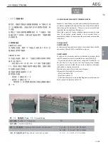
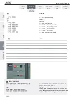
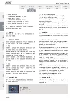
Otherwise the motor will recharge the springs --
Remove any padlocks from the racking panel.
-- Ensure the cabinet/panel door is closed.
Opera
Ɵ
on:
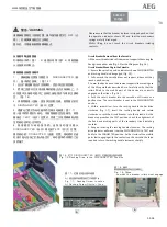
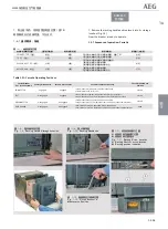
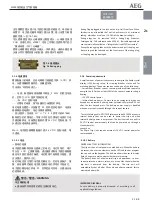
1. Remove the racking handle from its storage loca
Ɵ
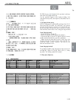
on (Fig. 1.9).
2. Pull out the torque bar from inside the handle and extend
the grip arm (Fig. 1.10).
3. Open the racking aperture shu
Ʃ
er by inser
Ɵ
ng and rota
Ɵ
ng
a
Ň
at screwdriver by 90°. (see Fig.1.11)
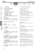
4 . Insert the racking handle and rotate counterclockwise.
The posi
Ɵ
on indicator moves from the CONNECTED through
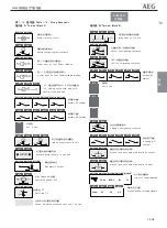
the TEST (Fig. 1.11B) to DISCONNECTED posi
Ɵ
ons.
NOTICE: When the racking handle is inserted in the racking
sha
Ō
, the circuit breaker cannot be operated in any posi
Ɵ
on
between
CONNECTED and DISCONNECTED.
Removing the handle automa
Ɵ
cally resets the racking handle
shu
Ʃ
er.
5. From the DISCONNECTED posi
Ɵ
on, con
Ɵ
nue turning the
racking handle an
Ɵ
-clockwise un
Ɵ
l reaching a posi
Ɵ
ve stop.
NOTICE: Ensure that the closing springs are fully discharged
(spring charge indicator should show 'Discharged') before
a
Ʃ
emp
Ɵ
ng to withdraw from the DISCONNECTED posi
Ɵ
on.
6. The circuit breaker is now in the maintenance posi
Ɵ
on (Fig.
1.12).
In this posi
Ɵ
on the cabinet/panel door can be opened and
means for li
Ō
ing can be a
Ʃ
ached to the li
Ō
ing hooks which
can be pulled out from the le
Ō
and right top of the breaker
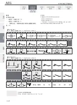
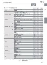
..see Table 1.21
1.4.6 Circuit breaker inser
Ɵ
on
Prepara
Ɵ
on:
-- Remove padlocks from the draw out support slides.
-- Remove all other padlocks from the casse
Ʃ
e.
-- Deac
Ɵ
vate any casse
Ʃ
e keylocks.
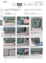
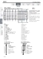
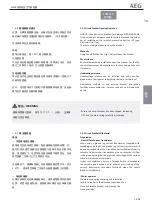
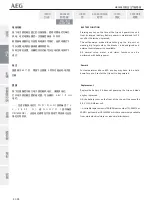
1. Carefully place the breaker on the fully extended draw out
support slides, taking care that the rollers are correctly
engaged. (Fig.1.12)
2. Remove any s
Ɵ
ll a
Ʃ
ached li
Ō
ing means from the device.
3. Push the breaker into the casse
Ʃ
e by applying pressure to
the front fascia (le
Ō
and right top area) un
Ɵ
l the mo
Ɵ
on
comes to an end.
4. Close the cabinet/panel door.
5. Prepare the casse
Ʃ
e and racking handle as men
Ɵ
oned
above (point 1 through 4) and insert the handle into it's
aperture.
6. Rota
Ɵ
ng the racking handle clockwise moves the breaker in.
It can be moved from the disconnect posi
Ɵ
on to the test
posi
Ɵ
on and further to the connected posi
Ɵ
on, as indicated by
the posi
Ɵ
on indicator (Fig. 1.11B).

