LOCKS
BREAKER ME10
INTRO
BREAKER
ACCESSORIES
TESTS
APPENDIX
TRIP UNIT
GENER
AL
C
OILS
MO
TOR
C
ONT
A
CTS
O
THER
4.1-02
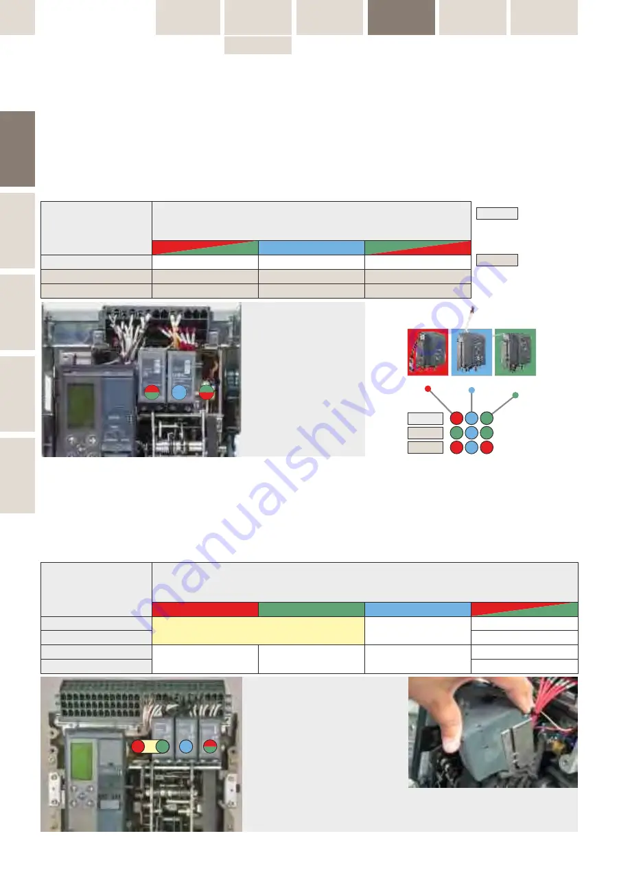
Table 4.0.1: Coil Combinations
NI:
Network Interlock
ST...:
Shunt Release continuous
SST.:
Shunt Release Impulse
UVR:
Undervoltage release
CC:
Closing coil
CCC:
Command closing coil
RRC:
Remote Reset Coil
ME10 Envelope T | Baugröße T | Taglia T
Fig.4.3: Standard Device Location
B) Shunt release
C) Closing Coils
D) Undervoltage Release
Abb.4.3: Standard Gerätelagen
B) Arbeitsstromauslöser
C) Abrufmagnet
D) Unterspannungs-Auslöser
Fot.4.3: Umiejscowienie urządzenia
B
)
W
yzwalacz napięciowy
C) Cewki zamykające
D)
P
odnapięciowy
Combination
Kombinationen
Combinazione
Position on Cover from the Left
Position in der Abdeckung von Links
Posizione sulla copertura, da sinistra
A
B
C
D
NI
CC or CCC
UVR1
ST1 / RRC
UVR1
ST2
1
2
3
4
CC or CCC
ST1
UVR2
Table 4.0.2: Coil Combinations
NI:
Network Interlock
ST...:
Shunt Release continuous
UVR:
Undervoltage release
CC:
Closing coil
CCC:
Command closing coil
RRC:
Remote Reset Coil
Tabelle 4.0.2: Modul-Kombinationen
NI:
Network Interlock
ST...:
Arbeitsstrom-Auslöser Dauerbetrieb
UVR:
Unterspannungs-Auslöser
CC:
Abrufmagnet
CCC:
Befehls-Abrufmagnet
RRC:
Fernreset-Auslöser
ME10 Envelope 1, 2 & 3 | Baugröße 1, 2 & 3 | Taglia 1, 2 & 3
Combination
Kombinationen
Combinazione
Position on Cover from the Left
Position in der Abdeckung von Links
Posizione sulla copertura, da sinistra
B
T1
T2
T3
D
UVR
UVR2
ST2 or SST2
C
CC or CCC
CC or CCC
CC or CCC
ST or SST
ST1 or SST1
UVR1
B
C
D
NI
A
B
C
D
Undervoltage
Release
Closing Coil
Shunt Release
T1
T2
T3
D
C
B
D
C
B
D
C
B
ST/SST
CC/CCC
UVR
Coil Installation
Modulmontage
Installazione bobina
Fig.4.3: Device Location
A) Network Interlock or Shunt release 1
B) Network Interlock or Undervoltage release 1
C) Closing Coils
D) Shunt Release or Undervoltage Release 2
Abb.4.3: Gerätelagen
A) Network Interlock oder Arbeitsstromauslöser 1
B) Network Interlock oder Unterspannungsauslöser 1
C) Abrufmagnete
D) Arbeitsstrom- oder Unterspannungs-Auslöser 2
Fig. 4.3: Posizione dispositivo
A) Interblocco di rete o bobina di sgancio a lancio di
corrente 1
B) Interblocco di rete o bobina di minima tensione 1
C) Bobine di chiusura
D) Bobina di sgancio a lancio di corrente o bobina di
minima tensione 2
Tabelle 4.0.1: Modul-Kombinationen
NI:
Network Interlock
ST...:
Arbeitsstrom-Auslöser Dauerbetrieb
SST.:
Arbeitsstrom-Auslöser Impulsbetrieb
UVR:
Unterspannungs-Auslöser
CC:
Abrufmagnet
CCC:
Befehls-Abrufmagnet
RRC:
Fernreset-Auslöser
Tabella 4.0.1: Combinazioni bobine
NI:
Interblocco di rete
ST:
Bobina a lancio di corrente continuamente alimentata
SST:
Bobina a lancio di corrente alimentata impulsivamente
UVR:
Bobina di minima tensione
CC:
Bobina di chiusura
CCC:
Bobina di chiusura a comando
RRC:
Bobina di reset
T1
T2 & T3
Possible with field mounted accessories
| Mit Zubehör vor Ort montierbar
| Per accessori montati sul campo
Standard of works variant
| Standard Normalausführung
| Versione standard
Tabella 4.0.1: Combinazioni bobine
NI:
Interblocco di rete
ST:
Bobina a lancio di corrente continuamente alimentata
UVR:
Bobina di minima tensione
CC:
Bobina di chiusura
CCC:
Bobina di chiusura a comando
RRC:
Bobina di reset


