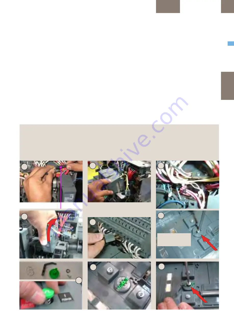
Optional Installation of Extra
LOCAL- "ON" Pushbutton.
8. Remove the existing dummy button by
removing the screw as shown in Fig. F.
9. Insert the pushbutton and the spring from the
front of the fascia. Fit them to the cover with the
supplied screw & washer as shown in Fig. G.
Installation of Electrical close switch (EC):
(..mandatory when an "Extra Local ON"
pushbutton is needed)
10. Place the EC-switch assembly over the
mechanism side sheet and locate in the two
locating holes as shown in Fig H.
11. Assemble the screw with washer as shown in
Fig J. Tighten the screw to torque 1,2Nm (0,9 ft-
lbs).
12. Plug the connector from the EC switch
assembly to the connector from the command
close coil (CCC) beside the PMU base as shown in
Fig. K.
Optionale Montage eines Drucktasters
zur Vorort EIN-Schaltung:
8. Entfernen Sie die vorhandenen Dummy-Taste,
mit der Schraube, wie in Abb. F gezeigt.
9. Stecken Sie den Drucktaster und die
Druckfeder von der Frontseite in die Schalter-
Abdeckung ein. Verbinden Sie die Teile an der
Abdeckung mit Schraube und Unterlegscheibe,
wie in Abb. G gezeigt.
Die Montage des Elektro-Schliessschalter (EC):
(..erforderlich, wenn ein "Vorort-Drucktaster"
benötigt wird)
10. Schieben Sie die EC-Schaltermontageeinheit
über den Mechanikträger zu den zwei
Einstecklöchern wie in Abb. H zu sehen.
11. Setzen Sie die Schraube mit Scheibe, wie in
Abb. J gezeigt ein. Ziehen Sie die Schraube mit
1,2 Nm Drehmoment an.
12. Stecken Sie den Stecker des EC-Schalters
mit dem Abrufmagnetenstecker (CCC) neben der
PMU Basis, wie in Abb. K gezeigt, zusammen.
BREAKER ME10
ACCESSORIES
4
.1
C
OILS
4.1-13
7. Assicurarsi che lo spinotto sia collegato in
modo saldo e sia inserito nei terminali corretti.
Installazione pulsante aggiuntivo di "ON"
locale.
8. Rimuovere il falso pulsante svitando la vite
come mostrato in Fig. F.
9. Inserire il pulsante e la molla dalla parte
anteriore della copertura anteriore. Bloccarlo
sulla parte anteriore con la vite e la rondella in
dotazione come mostrato in Fig. G.
Installazione del contatto di chiusura elettrica
(CE):
(Obbligatorio quando è richiesto un pulsante
aggiuntivo di "ON" locale)
10. Posizionare il meccanismo del contatto EC
sopra la copertura laterale del meccanismo e
individuare nei due fori di posizionamento come
mostrato in Fig H.
11. Montare la vite con rondella come mostrato
in Fig. J. Serrare la vite con una coppia di 1,2 Nm
(0,9 ft-lbs).
12. Inserire il connettore del contatto CE nel
connettore dalla bobina di chiusura a comando
C
A
Plug marked CCC
Stecker mit CCC beschriftet / Spinotto marcato CCC
B
E
D
G
G
G
Fig. A: CCC-Steckermontage
Fig. B: CCC-Modulmontage
Fig. C: Verdrahtungslage
Fig. D: CCC Befestigen durch Einschnappen
Fig. E: Stecker an Hilfstrennblock einstecken
Fig. F: Blindtasterschraube rausschrauben
Fig. G: Drucktasterteile in Frontabdeckung
montieren.
F
- Dummy button screw
- Schraube Blindtaste
- Vite falso pulsante
Fig. A: CCC-Plug assembly
Fig. B: CCC-Coil assembly
Fig. C: wiring position
Fig. D: Closing Coil assembly
Fig. E: Secondary disconnect plug
Fig. F: Remove dummy button screw
Fig. G: Extra Local ON-Pushbutton assembly
Fig. A: Collegamento spinotto-CCC
Fig. B: Collegamento bobina-CCC
Fig. C: posizione collegamento
Fig. D: Montaggio bobina di chiusura
Fig. E: Morsetti di sezionamento ausiliari
Fig. F: Rimuovere la vite del falso pulsante
Fig. G: Montaggio pulsante aggiuntivo di "ON"
locale


