4.1.7 Network Interlock (NI)
Das Network Interlock Zubehör sperrt den
Leistungsschalter in der AUS-Stellung elektrisch
und mechanisch. Wenn dieses Gerät einen
Impuls erhält, sind alle lokalen Schalter-
Funktionen abgeschaltet, außer der Auslöse-
funktion bei jeder Art von Überstromfehlern.
Nach Eingang eines zweiten Impulses wird der
Ausgangszustand wieder hergestellt. Die
Präsenz der Netzspannung hat keine
Auswirkungen auf die Sperrung und/oder die
Wiederherstellung des Ausgangszustandes.
Jedes Gerät hat eine direkte Rückstelltaste, die
nur nach Entfernung der Schalterabdeckung
ausgelöst werden kann.
Zum Zeitpunkt der Drucklegung dieses
Handbuchs ist das Network Interlock nur als
werkseitig eingebautes Zubehör verfügbar.
Wenden Sie sich bitte an Ihr nächstes AEG-Büro
für Vorort-montierbare Ausführungen.
Das NI benötigt die linken 2 Modulplätze eines A-
und eines U-Auslösers.
Installation des Network Interlock
1. Der Leistungsschalter muss sicher elektrisch
isoliert und vollständig in die TRENN-Stellung
gebracht werden.
2. Entfernen Sie die Schalter Frontabdeckung
wie unten erklärt.
3. Dieser NI-Zubehörartikel benötigt zwei
Steckplätze auf der Einsteckplatte, immer den
1.+2. Standort wie in Abb. A + F dargestellt
4. Kippen Sie den NI-Baustein nach vorn und
lassen sie die vorderen Haken in die
Einsteckplatte, wie in der Abb. B gezeigt,
eingreifen.
5. Kippen Sie das NI-Gerät rückwärts bis die
hinteren Haken in den Schlitzen in der
Einsteckplatte, wie in der Abb. C dargestellt,
einrasten.
6. Schließen Sie den Verdrahtungs-
Eingangsstecker an die mit A5-A6 und A7-A8
gekennzeichneten Verdrahtungsklemmen an
dem sekundären Trennblock A, wie in Abb. D
gezeigt, an. Schließen Sie die NI-Status-
4.1.7 Network Interlock Device (NI)
The Network Interlock Device locks the breaker
in OFF position electrically and mechanically.
When this device receives a pulse all local
breaker functionality is disabled except the
tripping of the device on any over current fault.
On the receipt of a 2nd pulse normal operation is
re-instated. The presence of mains power does
not effect the locking and/or reinstatement of
this device. Each device has a local RESET button
that only can be accessed after breaker cover
removal.
As indicated here the device can be mounted in
the field but at the moment that this document
was published it was only available as factory
mounted component.
Please contact the nearest AEG office for field
mounted variants. It has the volume of two
releases (Shunt/Undervoltage).
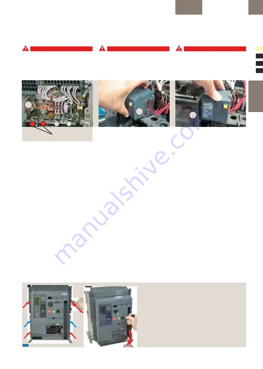
Installation of Network Interlock
1. The breaker should be safely isolated and fully
withdrawn to disconnected position.
2. Remove the fascia as explained.
3. This accessory uses two locations of the coils
on the mechanism top plate at 1.+ 2. locations
as shown in Fig. A+F
4. Tilt the NI forward and engage the front hooks
into the mechanism top support plate as shown
in the Fig. B.
5. Tilt the device backwards until the rear hooks
engage in the slots on the mechanism top
support plate as shown in the Fig. C.
6. Connect the input wire assembly plugs to the
A5-A6 and A7-A8 locations marked on the
secondary disconnect block A as shown in Fig. D.
Connect the NI status switch wire assembly
4.1.7 Dispositivo di interblocco di rete
(NI)
Il dispositivo di interblocco di rete blocca
l'interruttore in posizione OFF elettricamente e
meccanicamente. Quando questo dispositivo
riceve un impulso, tutte le funzionalità
dell'interruttore locale vengono disabilitate,
tranne lo scatto del dispositivo in caso di una
qualsiasi anomalia di sovracorrente. Alla
ricezione di un secondo impulso viene
ripristinato il funzionamento normale. La
presenza dell'alimentazione di rete non influenza
il blocco e/o la rimessa in servizio di questo
dispositivo.
Ogni dispositivo dispone di un pulsante di reset
locale cui è possibile accedere solo dopo la
rimozione della copertura dell'interruttore. Come
indicato, il dispositivo può essere montato in
loco ma al momento della pubblicazione di
questo documento è disponibile solo come
elemento montato in fabbrica. Si prega di
contattare l'ufficio AEG più vicino per
informazioni sulle versioni da montare in loco. Il
dispositivo ha un volume pari a due sganciatori
(a bobina di lancio di corrente/di minima
tensione).
Installazione dell'interblocco di rete (NI)
1. L'interruttore deve essere isolato in modo
sicuro e completamente estratto in posizione
DISCONNECTED.
2. Togliere la copertura anteriore come indicato.
3. Questo accessorio utilizza due posizioni delle
bobine sulla piastra superiore del meccanismo
nelle sedi 1. + 2. Come indicato in Fig. A + F
4. Inclinare l'NI in avanti e agganciare i fermi
anteriori nella piastra di supporto superiore del
meccanismo come mostrato in Fig. B.
5. Inclinare il dispositivo all'indietro finché i fermi
posteriori si inseriscono nelle fessure della
piastra di supporto superiore del meccanismo
come mostrato in Fig. C
6. Collegare gli spinotti del cavo di ingresso nelle
posizioni A5-A6 e A7-A8 contrassegnate sulla
morsettiera di sezionamento ausiliaria A, come
C
B
1
2
3
4
NI mounting location 1+2
NI Montageplatz 1+2
NI spazio di montaggio 1+2
A
BREAKER ME10
ACCESSORIES
4
.1
C
OILS
4.1-15
Instruction sheet
Gebrauchsanleitung
Foglio istruzioni
Fig.1
Fig.2
C
B
A
Removal of Front cover
1
. Remove pad locks, installed if any.
2.
Unscrew the 6 [Env. T = 4] screws (6Nm, 4.42ft-lbs) using a Pozidrive screw driver
as shown in Fig. A&B.
3.
Rotate the charging handle down and slide the front
cover over the handle to remove out as shown in Fig. C.
Abbau der Frontabdeckung
1
. Entfernen Sie installierte Vorhängeschlösser.
2.
Lösen Sie die 6 [Baugr. T = 4] Schrauben (6Nm) mit einem Pozidrive-
Schraubenzieher wie in Abb. A&B dargestellt.
3.
Ziehen Sie den Spannhebel nach
unten, während Sie die Abdeckung für den Abbau nach oben über den Hebel heben,
wie in Abb. C.
Rimozione della copertura anteriore
1.
Se installati, rimuovere I lucchetti.
2.
Svitare le 6 [Taglia T = 4] viti (6Nm, 4.42ft-lbs) utilizzando un cacciavite Pozidriv
come mostrato in Fig.A&B.
3.
Abbassare la leva di carica manuale e far scorrere
la copertura anteriore sopra la maniglia per rimuoverla, come mostrato in Fig. C.
Envelope 1-3 only | nur bei Baugröße 1-3 | solo per Taglia 1-3
ME10: Envelope 1, 2 & 3 only
ME10: nur für Baugröße 1, 2 & 3
ME10: solo per taglia 1, 2 & 3


