5.3.3
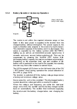
Bypass Operation
If the inverter is overloaded or if overtemperature is detected,
e.g. also if an inverter defect is detected, voltage is supplied
to the load via the bypass that switches on automatically. This
is signalled by the LED BYPASS symbol.
This function is also referred to as passive redundancy. It
protects against total failure of the voltage supply on the
protected busbar, however in the operating status that is now
attained, mains faults would have a direct effect on the load.
As a result, the electronics continuously attempt to switch
back to "online" / normal operating status (e.g. when the
overload or overtemperature no longer applies).
The bypass is a link that switches extremely rapidly. It is
located between the load and the mains. The associated
synchronisation unit in the bypass ensures that the frequency
and phase of the inverter voltage is synchronised with the
mains.
~
~
~
REC
Battery
charger
INV
Autom.
bypass
Safe busbar:
Load
Mains
Battery
Power circuit with
faulty INV
Diagram
i
The LED bar graph functions as display for USP
utilisation. The signal goes off during this
operations status every 2 seconds.
34
Summary of Contents for PROTEC C. 1000 R(S)
Page 13: ...3 3 CE Certificate 13 ...
Page 14: ...14 ...


