5.4
Interfaces and communication
5.4.1
Data line protection RJ11 and RJ45
The incoming data lines are connected to the “IN” line at the
rear of the UPS. The “OUT” line is connected via data line
with your terminal.
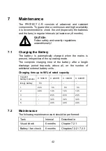
i
The data line protection supports networks with
transfer rates between 10 and 100 MBit/s.
5.4.2
Computer interfaces RS232
The UPS offers various interfaces to manage the system and
to comfortable readout state information and important
parameters. The communication protocol is optimized for
operation with the shutdown and UPS management software
“CompuWatch” from AEG. To connect to the UPS to your
computer use the provided RS232 communication cable by
attaching them to a free serial port of your pc.
RS232 interface: The interface is connected via a 9 pole
Sub-D connector on the back of the unit (pos. 4 p. 23 / 24).
PINs: 2 = TxD; 3 = RxD; 5 = GND.
5.4.3
Communication Slot
If the cover on the rear of the UPS is removed (pos. 8 p. 25),
additional optionally available communication components
can be installed there.
AS/400 board:
Slot card with status messages, realised via
potential-free relay contacts
SNMP board:
Slot card for direct connection of the UPS to
the Ethernet network with RJ 45 (TCP/IP)
Details can be found in the description enclosed with the
particular optional component. Other boards are in preparation.
i
Using the communication slot deactivates the
RS232 interface of chapter 5.4.2.
36
Summary of Contents for PROTEC C. 1000 R(S)
Page 13: ...3 3 CE Certificate 13 ...
Page 14: ...14 ...


