3.5
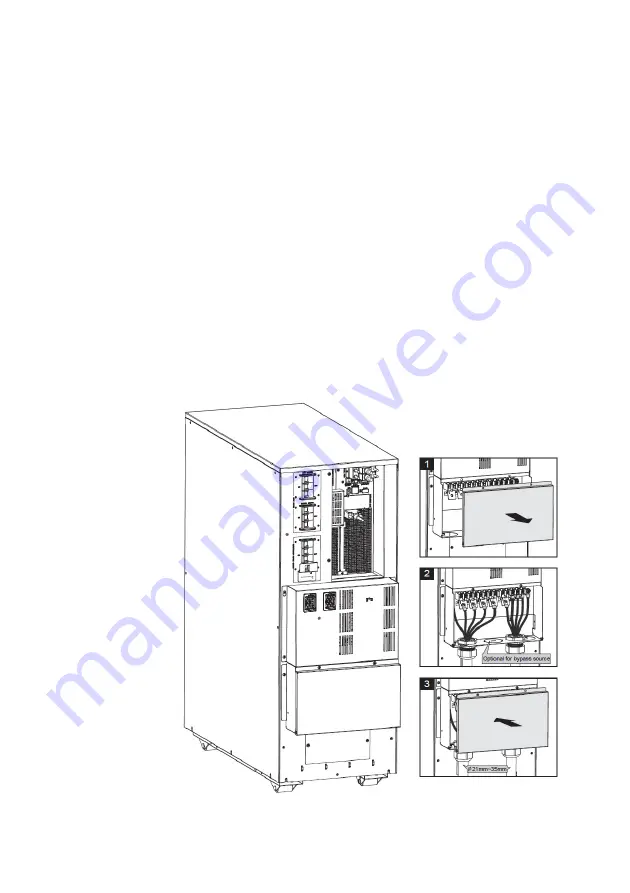
Gland kit installation
Before Gland kit installation, select the appropriate cables according to the
wiring table in section 3.4.2
1. Open the terminal block cover
2. Assemble the glands and cables to the gland bracket according to
input/output Mode & Connect the wires of cables to the terminal
block/busbar according section 3.4.2.
3. Re-lock the terminal block cover back
Summary of Contents for PROTECT 1 LCD
Page 5: ...Revision Change Date Name 00 Created 21 07 2021 AN ...
Page 6: ......
Page 32: ... Connect with user s own EBM Connect user s own EBM to UPS with Battery cable if configured ...
Page 37: ... 3 3 configuration dual source 3 1 configuration single source ...
Page 38: ... 3 1 configuration dual source 1 1 configuration single source ...
Page 40: ...Note Note Note Note Common battery configuration is not suitable for standard model ...
Page 46: ...5 3 Menu structure ...


