9
EN
2.2 System description
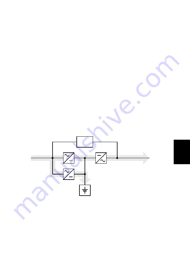
The UPS is connected between the public network and the
power load segments to be protected.
The rectifier is powered from the mains and converts the AC
voltage into a stabilized DC voltage to feed the inverter. The
circuitry technology used (PFC) enables sinusoidal current
consumption, thus allowing a low circuit feedback operation. A
separate, second rectifier (charger) based on switching power
supply technology recharges or maintains the charge of the
battery in the intermediate circuit. Due to the special circuitry
technology used in this charger
/ rectifier, the harmonics of the
charging current are reduced significantly. Additionally, a sleep
mode considerably increases the service life of the battery. The
inverter converts the DC voltage into a sinusoidal AC voltage. In
combination with digital signal processor technology and
extremely high pulse rate IGBT-power semiconductors in the
inverter, a microprocessor-controlled regulator on the basis of
pulse-width modulation (PWM) guarantees a voltage system of
highest quality and availability on the secured busbar.
Battery
Load REC
REC
INV
Mains
Schematic
diagram
Secured
busbar:
Load
Power circuit
with mains supply
autom.
Bypass
In the event of mains problems (e.g. power outages), power is
supplied to the load segment without any interruption from the
inverter, which now uses the battery. Since no switching is
required, the load segment experiences no power supply
interruption at all.
Summary of Contents for protect d. 1000
Page 2: ...2 ...
Page 21: ...21 EN 3 3 CE certificate ...
Page 73: ...73 EN 12 3 Notes ...
Page 74: ...74 ...
Page 75: ...75 EN ...


