background image

36 


DE 


Einsetzen des neuen Batteriesystems 

Führen Sie die oben beschrieben Schritte in umgekehrter Reihenfolge 

aus. 

  Aus Sicherheits- und Effiziensgründen nutzen Sie bitte auschließ-

lich die Batterieaustauschkits der AEG PS. 

  Fügen Sie die Steckverbindung 

fest

 zusammen! 


Entsorgung von gebrauchten Batterien und Akkumulatoren  
(anzuwenden in den Ländern der Europäischen Union und anderen europä-
ischen Ländern mit einem separaten Sammelsystem für diese Produkte). 
 
Das Symbol auf dem Akkumulator oder der Verpackung weist darauf hin, 
dass diese nicht als normaler Haushaltsabfall zu behandeln sind. Ein zu-
sätzliches chemisches Symbol „Pb“ (Blei) unter der durch-gestrichenen 
Mülltonne bedeutet, dass der Akkumulator einen Anteil  
von mehr als 0,4 % Blei enthält. 
 
Durch Ihren Beitrag zum korrekten Entsorgen dieser Akkumulatoren schüt-
zen Sie die Umwelt und die Gesundheit Ihrer Mitmenschen.  
Umwelt und Gesundheit werden durch falsches Entsorgen gefährdet. Mate-
rialrecycling hilft, den Verbrauch von Rohstoffen zu verringern. 
Bei Produkten, die aufgrund ihrer Sicherheit vor Datenverlust eine  
ständige Verbindung zur eingebauten Batterie benötigen, sollte die Batterie 
nur durch qualifiziertes Servicepersonal ausgetauscht werden. 
Um sicherzustellen, dass die Batterie korrekt entsorgt wird, geben  
Sie das Produkt zwecks Entsorgung an einer Annahmestelle für das Recyc-
ling von Akkumulatoren ab.  
 

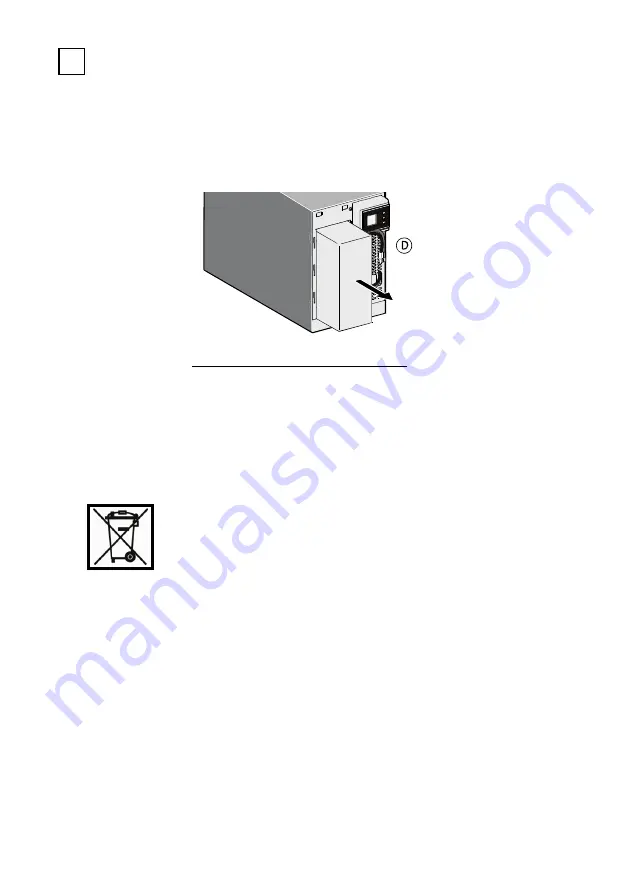
D - Ziehen Sie das Batterie-

system an der Plastikver-

schalung nach vorne und 

ersetzen Sie das 

      Batteriesystem durch ein 

Austauschkit. 

Summary of Contents for Protect NAS

Page 1: ...BETRIEBSANLEITUNG OPERATING INSTRUCTIONS DE EN Protect NAS ...

Page 2: ...2 DE ...

Page 3: ...Solutions entschieden haben Die nachfolgenden Sicherheitshinweise sind wichtiger Bestandteil der Betriebsanleitung und werden Sie vor Problemen durch Fehlbedienung oder vor möglichen Gefahren schützen Lesen Sie deshalb diese Anleitung vor der ersten Inbetriebnahme sorgfältig durch ...

Page 4: ...icht Anschlüsse Bedien Anzeigeelemente22 5 1 Vorderansicht 22 5 2 Rückseitige Ansicht Anschlüsse 22 6 Inbetriebnahme 23 6 1 Aufstellung 23 6 2 Netzanschluss 24 6 3 Verbraucheranschluss 24 7 Betrieb und Bedienung 26 7 1 Erstinbetriebnahme 26 7 2 Bedientableau 26 7 2 1 Überblick 26 7 2 2 Display Beschreibung 27 7 2 3 Einstellungen 28 7 2 4 Funktionen 29 7 2 5 Akustische Signale 29 8 Schnittstellen u...

Page 5: ...tkontrolle 33 10 2 2 Batteriekontrolle 34 10 2 3 Luft ein auslässe 34 10 3 Batteriewechsel 34 11 Lagerung Demontage und Entsorgung 38 11 1 Lagerung 38 11 2 Demontage 38 11 3 Entsorgung 38 12 Anhang 40 12 1 Sachwortverzeichnis technische Begriffe 40 12 2 Stichwortregister 42 ...

Page 6: ...ehlerhaft werden nach unserer Wahl nachgebessert oder ersetzt werden es sei denn der Fehler ist eindeutig nicht durch AEG Power Soluti ons zu vertreten Die Reparatur oder der Austausch eines fehlerhaften Produkts oder von Teilen davon verlängert nicht den ursprünglichen Ge währleistungszeitraum Die 24 monatige Gewährleistung gilt weltweit und beginnt aber dem Datum des Erwerbs des Produktes wobei ...

Page 7: ...bernimmt AEG Power Solutions keinerlei Haftung für sonstige Schäden sofern diese nicht unter das Produkthaftungsgesetz fallen oder eine Schädigung von Leib oder Leben vorliegt Ebenso haftet AEG Power Solutions lediglich bei Vorliegen von Vorsatz oder grober Fahr lässigkeit Im Falle allgemeiner Fahrlässigkeit ist die Haftung von AEG Power Solutions auf vorhersehbare vertragstypische Schäden bis max...

Page 8: ... Arbeiten Gefährdungen für Personen und Material nicht auszuschließen werden diese Tätigkeiten durch Piktogramme ge kennzeichnet deren Bedeutung den Sicherheitsbestimmungen in Kapitel 3 zu entnehmen ist HOTLINE Sollten Sie nach dem Lesen der Betriebsanleitung noch Fragen haben wenden Sie sich bitte an Ihren Händler oder an unsere Hotline Tel 49 2902 763100 Internet www aegps com COPYRIGHT Weiterga...

Page 9: ...führung Aktivierbarer Green Mode zur Steigerung der Batterieverfügbarkeit Intelligentes Monitoringsystem mit USB Schnittstelle als HID Power Device für softwareunabhängiges USV Management 2 2 SYSTEMBESCHREIBUNG Die USV wird zwischen dem öffentlichen Netz und den zu schützenden Verbrauchern angeschlossen Bei normalen Betriebsbedingungen bei denen der Protect NAS mit Netzspannung versorgt wird hält ...

Page 10: ...rt dabei so lange Spannung bis die Batterie entladen ist bzw Ihr EDV System ordnungsge mäß herunter gefahren und abgeschaltet wurde Diese Überbrückungszeit ist im Wesentlichen abhängig von der ange schlossenen Verbraucherlast Wenn die Netzversorgung wieder normale Werte aufweist schaltet die USV den Verbraucher wieder auf Netzspei sung Der Batterieladegleichrichter lädt dann die Batterie erneut au...

Page 11: ... A Anschluss Kaltgerätestecker USV Ausgang Nennausgangsspannung AVR Technik 220VAC 230VAC Voreinstellung 240 VA 10 6 Nennausgangsspannung im Batteriebetrieb 220VAC 230VAC Voreinstellung 240 VA 10 5 Frequenz im Batteriebetrieb 50 Hz 60 Hz 0 1 Hz Nennausgangsstrom bei 230 VAC 2 1 A Umschaltzeit bei Netzausfall 10 ms Spannungskurvenform Sinusförmig Überlastverhalten VI Betrieb 105 bis 120 für 300 s 1...

Page 12: ...vanten Messwerten Ein und Ausgangsspannung V Auslastung Verbraucherlast k VA und k W sowie Überbrückungszeit bei aktueller Last min zusätzlich 2 Bargraphen für Auslastung und aktuelle Batteriekapazität beleuchteter Ein Aus Taster Shutdown Software auf CD 5er Netzwerklizenz im Lieferumfang für alle gängigen Betriebssysteme u a Windows Linux Mac Alarmmeldungen akustisch optisch Akustischer Signalgeb...

Page 13: ...leitungen RJ11 Telefon Fax Modem RJ45 Ethernet 10 MBit s 100 MBit s Netzeingang IEC 320 C14 Verbraucherabgänge 4 x IEC 320 C13 Display LCD Display mit 3 Hauptbereichen Gehäusefarbe Schwarzes Metallgehäuse mit silberner Frontblende Netto Bruttogewichte ca 6 8 kg 7 8 kg Abmessungen B x H x T netto 150 mm x 209 mm x 240 mm Abmessungen B x H x T brutto Verpackung 199 mm x 295 mm x 301 mm Lieferumfang ...

Page 14: ...e bestimmungsgemäß sicherheits und gefahrenbewusst unter Beachtung der Betriebsanleitung Beseitigen Sie umgehend Störungen welche die Sicherheit beeinträchtigen können In dieser Anleitung werden folgende Piktogramme benutzt Hinweis Gefahr Bei Gefahr für Leib und Leben des Bedieners Hinweis Achtung Bei Verletzungsgefahr sowie Gefährdung von Gerät und Geräteteilen Hinweis Information Nützliches und ...

Page 15: ...USV eine eigene interne Stromversorgung besitzt Batterie Das Gerät muss aus Gründen des Personenschutzes ordnungsgemäß geerdet werden Der Protect NAS darf nur mit einer VDE geprüften Netzanschlussleitung mit Schutzleiter im Lieferumfang enthalten an 220 V 230 V 240 V Wechselspannungsnetzen mit Schutzerdung betrieben bzw angeschlossen werden Verbrennungsgefahr Die Batterie weist hohe Kurzschlussstr...

Page 16: ...nden abwarten Niemals Netzeingang und USV Ausgang miteinander verbinden Dafür Sorge tragen dass keine Flüssigkeiten oder Fremdkörper in die Gehäuse gelangen Die Be und Entlüftungsöffnungen des Gerätes nicht versperren Darauf achten dass z B Kinder keine Gegenstände in die Belüftungsöffnungen stecken Keine Haushaltsgeräte wie zum Beispiel Haartrockner an die USV anschließen Vorsicht auch bei Betrie...

Page 17: ... Batterien nicht öffnen oder beschädigen frei gewordener Elektrolyt ist schädlich für Haut und Augen und kann giftig sein Batterien können Stromschläge und hohe Kurzschlussströme verursachen Treffen Sie daher folgende Vorsichtsmaßnahmen wenn Sie mit Batterien arbeiten Legen Sie Uhren Ringe und andere Gegenstände aus Metall ab Verwenden Sie nur Werkzeug mit isolierten Griffen Verbraucher nicht über...

Page 18: ...18 DE Schalten Sie zur Sicherheit Ihrer Person die USV niemals ohne vorherige Erdung des Gehäuses bzw ordnungsgemäß vollzogener Netz anbindung ein ...

Page 19: ...19 DE 3 3 CE ZERTIFIKAT ...

Page 20: ... innerhalb von acht Tagen ab Lieferung über den AEG Repräsentanten bzw Händler zu melden Überprüfen Sie den Inhalt der Lieferung auf Vollständigkeit Protect NAS Netzanschlussleitung mit Schutzkontaktstecker Geräteanschlussleitung USB Kommunikationsleitung Management Software CompuWatch auf CD Betriebsanleitung Abweichungen bitten wir unserer Hotline s Seite 8 zu melden Die Originalkartonage bietet...

Page 21: ...ion gewähr leistet ist Zuluftöffnungen nicht versperren Die USV sollte nicht bei einer Umgebungstemperatur 35 C betrieben werden Stellen Sie die Geräte in einem Raum auf der trocken relativ staubfrei und frei von chemischen Dämpfen ist Stellen Sie sicher dass keine magnetischen Speichermedien in der Nähe des Protect NAS gelagert und oder betrieben werden Überprüfen Sie auf dem Typenschild ob die S...

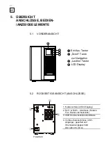
Page 22: ...EELEMENTE 1 Netzanschluss USV Eingang 2 RJ11 RJ45 Anschluss Telefon Fax Router und Netzwerk 3 USB Kommunikationsschnittstelle 4 Verbraucheranschlüsse USV Abgänge gepuffert und Überspannungsgeschützt IEC 320 C13 10 A Ein Aus Taster Scroll Taste zur Navigation Lautlos Taster LCD Display Protect NAS ...

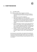
Page 23: ...mperaturen vermeiden Um die Gebrauchsdauer der Batterien zu maximieren ist eine Umgebungstemperatur von 0 35 C zu empfehlen ideal Raumtemperatur Die Einheiten nicht direkter Sonneneinstrahlung aussetzen oder in der Nähe ander weitiger Wärmequellen wie z B Heizkörper betreiben Einheiten vor äußeren Einwirkungen insbesondere Feuchtigkeit und Staubeinwirkung schützen Beachten Sie diesbzgl auch die Hi...

Page 24: ...ucher an die USV anschließen lassen Sie die USV mindestens sechs Stunden ohne Last am Netz Dadurch wird die Batterie vollständig geladen und die größte Effizienz gewährleistet 6 3 VERBRAUCHERANSCHLUSS Bevor Sie den Anschluss der Verbraucher an die USV vornehmen schalten Sie die USV aus und trennen diese vom Netz Kontrollieren Sie bitte dass die angegebene Nennleistung auf dem Typenschild größer od...

Page 25: ...inem totalen Verlust der USV Funktionen führen Vermeiden Sie auch kurzfristige Geräteüberlastungen wie sie z B durch Anschluss eines Laserdruckers oder eines Laserfaxgerätes entstehen können Schließen Sie keine Haushaltsgeräte oder Werkzeug maschinen an die USV an Niemals zusätzliche Verbraucher an die USV anschließen oder zuschalten wenn Netzausfall vorliegt d h die USV im Notstrombetrieb arbeite...

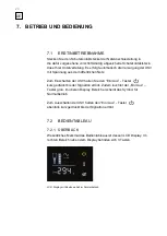
Page 26: ...V halten Sie den Ein Aus Taster kurz gedrückt bis der Signalton ertönt Zudem leuchtet der Ein Aus Taster grün im oberen Display Bereich erscheint das Symbol für Normalbetrieb Zum Ausschalten der USV halten den Ein Aus Taster ebenfalls kurz gedrückt bis der Signalton ertönt 7 2 BEDIENTABLEAU 7 2 1 ÜBERBLICK Wesentliches Merkmal des Bedientableaus ist dessen LCD Display Im rechten Bereich neben dem ...

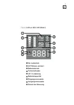
Page 27: ...27 DE 7 2 2 DISPLAY BESCHREIBUNG Normalbetrieb AVR Modus aktiviert Batteriebetrieb Fehlerindikation USV Auslastung Batteriekapazität Eingangsmesswerte Ausgangsmesswerte Einheit der Messung ...

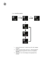
Page 28: ... die Scroll Taste für 5 sek bis Out im Display erscheint 2 Wählen Sie durch Drücken der Scroll Taste die gewünsch te Ausgangsspannung 220VAC 230VAC voreingestellt 240VAC 3 Warten Sie 5 sek bis das Display zum Ausgangspunkt zu rückkehrt 1 2 3 ...

Page 29: ...eine Last an die USV angeschlossen ist wird die USV automatisch nach 5 Minuten heruntergefahren um Energie zu sparen Die USV startet erneut sobald die Netzspannung wieder zur Verfügung steht Die Aktivierung der Green Power Funktion ist ausschließlich über die mitgelieferte Software CompuWatch möglich 7 2 4 3 AVR Automatische Spannungsregulierung Ist die Netzeingangsspannung unzureichend wird die A...

Page 30: ...wendung des HID Power Device Protokolls ist es nicht immer zwingend notwendig eine zusätzliche Software z B CompuWatch zu installieren Intelligente Verbraucher wie z B das NAS System erkennen dass eine USV angeschlossen ist und können mit dieser kommunizieren Über die Benutzeroberfläche des NAS Systems kann der Betriebszustand oder die Backup Zeit der USV abgefragt werden Zusätzlich bietet sich de...

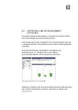
Page 31: ...ss die Verfügbarkeit der EDV Komponenten sowie die Datensicherheit gewährleis tet werden Die Shut Down Software CompuWatch unterstützt diverse Betriebssysteme u a Windows 7 8 10 Linux RedHat Novell Netware IBM AIX HP UX SUN Solaris Mac OS X Details zur Installation unter den diversen Betriebssystemen entnehmen Sie dem auf der CD befindlichen Handbuch Download von Updates über www aegps de Abb Beis...

Page 32: ... Überlast der USV Stellen Sie sicher das die Last der USV der spezifischen Kapazität entspricht siehe technische Daten Netzanschlussstecker ist lose Stecken Sie die Netzanschlussleitung richt ein Bei Netzausfall wird die Überbrückungszeit geringer Überlast der USV Entfernen Sie alle nicht kritischen Lasten Batteriespannung zu gering Laden Sie die Batterie 6 Stunden oder mehr Batterie defekt aufgru...

Page 33: ...Batterie wird automatisch durch die Präsenz des Netzes unabhängig von der Betriebsart geladen Die komplette Aufladezeit der Batterie beträgt ca 6 Stunden 10 2 KONTROLLEN Folgende Wartungsarbeiten sollten durchgeführt werden Tätigkeit Zyklus Beschrieben in Sichtkontrolle 6 Monate Kapitel 10 2 1 Batterie Lüfterkontrolle Luftei auslässe 6 Monate Kapitel 10 2 2 10 2 3 10 2 1 SICHTKONTROLLE Bei den Sic...

Page 34: ...eit durch Die Last sollte hierbei immer den annähernd gleichen Leistungsbedarf aufweisen Bei drastisch abfallenden Zeiten gegenüber der vorherigen Messung kontaktie ren Sie bitte unsere Hotline s Seite 8 10 2 3 LUFT EIN AUSLÄSSE Die Luftein auslässe sind regelmäßig auf Staubanfall zu überprüfen Bei verstopften Zuluftöffnungen sind diese zu reinigen 10 3 BATTERIEWECHSEL Achtung Eine Batterie kann U...

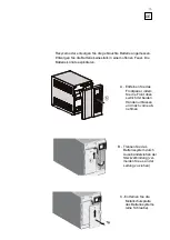
Page 35: ...Batterie könnte explodieren A Entfernen Sie das Frontpanel indem Sie die Front oben seitlich mit beiden Händen umfassen und nach vorne ab nehmen B Trennen Sie das Batteriesystem durch Auseinanderziehen der Steckverbindung ver meiden Sie es an der Leitung zu ziehen C Entfernen Sie die Metallschutzplatte des Batteriesystems eine Schraube ...

Page 36: ...gestrichenen Mülltonne bedeutet dass der Akkumulator einen Anteil von mehr als 0 4 Blei enthält Durch Ihren Beitrag zum korrekten Entsorgen dieser Akkumulatoren schüt zen Sie die Umwelt und die Gesundheit Ihrer Mitmenschen Umwelt und Gesundheit werden durch falsches Entsorgen gefährdet Mate rialrecycling hilft den Verbrauch von Rohstoffen zu verringern Bei Produkten die aufgrund ihrer Sicherheit v...

Page 37: ...Recycling von Akkumulatoren erhalten Sie von Ihrer Gemeinde den kommunalen Entsorgungsbetrieben oder dem Geschäft in dem Sie das Produkt erworben haben Entsorgungshinweis Entsorgen Sie nur entladene Batterien beim Handel oder den Kommunen ...

Page 38: ...agerung an das Netz angeschlossen werden um ein völliges Aufladen der Batterie zu gewährleisten Die Aufladezeit sollte mindestens der in Kapitel 10 1 genannten Zeit ent sprechen 11 2 DEMONTAGE Die Demontage erfolgt nach der Montagebeschreibung in umgekehrter Reihenfolge 11 3 ENTSORGUNG Bitte entsorgen Sie bei endgültiger Außerbetriebsetzung im Interesse des Umweltschutzes und der Wiederverwertung ...

Page 39: ...en werden muss Durch Ihren Beitrag zum korrekten Entsorgen dieses Produkts schützen Sie die Umwelt und die Gesundheit Ihrer Mitmenschen Umwelt und Gesundheit werden durch falsches Entsorgen gefährdet Materialrecycling hilft den Verbrauch von Rohstoffen zu verringern Weitere Informationen über das Recycling dieses Produkts erhalten Sie von Ihrer Gemeinde den kommunalen Entsorgungsbetrieben oder dem...

Page 40: ...ansistors Klasse D siehe Geräteschutz LED Light Emitting Diode Elektronisches Halbleiter Bauelement im Sprachgebrauch als Leuchtdiode bezeichnet Verwendung zur optischen Signalisierung PFC Power Factor Correction Schaltungstechnik zur Minimierung von Netzrückwirkungen insbesondere wichtig bei Anschlus von nichtlinearen Lasten PWM Puls Weiten Modulation hier Schaltungstechnik zur Generierung einer ...

Page 41: ...chwankungen jedoch wird die Netzspannung durch elektronische passive Spannungsregelgeräte aufbereitet Frühere Bezeichnung LINE INTERACTIVE VFI Output Voltage and Frequency Independent from main supply Der USV Ausgang ist unabhängig von Netzspannungs und Frequenzschwankungen Frühere Bezeichnung ONLINE ...

Page 42: ...ebszustände 9 Normalbetrieb 25 C R CE Erklärung 18 Richtlinien 12 13 D S Display 26 Schnittstellen PC 12 29 Sicherheitshinweise 14 E Signalisierung 14 24 28 Einstellungen 27 Störung 31 Systembeschreibung 9 10 G Geräteüberlast 10 T Gewichte 12 Technische Daten 11 H U Hotline 8 Überbrückungszeit 12 Überlast 11 24 I USB 13 29 Erst Inbetriebnahme 25 Inhaltsverzeichnis 4 V Verbraucheranschluss 21 23 K ...

Page 43: ...43 DE NOTIZEN ...

Page 44: ...44 EN ...

Page 45: ... safety instructions are an important part of these operating instructions and will protect you against problems that may occur as a result of incorrect operation and against potential hazards You must therefore read these instructions carefully before carrying out initial commissioning ...

Page 46: ...4 2 Installation Site 62 5 Overview of Connections 63 Controls and Display Elements 63 5 1 Front View 63 5 2 Rear View Connections 63 6 Commissioning 64 6 1 Installation 64 6 2 Mains Connection 65 6 3 Load Connection 65 7 Operation and Control 67 7 1 Initial Commissioning 67 7 2 Control Panel 67 7 2 1 Overview 67 7 2 2 Display Description 68 7 2 3 Settings 69 7 2 4 Functions 70 7 2 5 Acoustic Sign...

Page 47: ...ry 74 10 2 Inspections 74 10 2 1 Visual Inspection 74 10 2 2 Battery Inspection 75 10 2 3 Air Inlets Outlets 75 10 3 Replacing the Battery 75 11 Storage Disassembly and Disposal 78 11 1 Storage 78 11 2 Disassembly 78 11 3 Disposal 78 12 Annex 80 12 1 Definitions of Technical Terms 80 12 2 Index 82 ...

Page 48: ...rranty period The warranty period starts from the date of purchase which is to be proven by the customer through provision of the purchase invoice If the customer cannot provide the purchase invoice then the date of purchase by the distributor shall serve as starting point for calculation of the warranty period In the event of a defect AEG PS shall undertake to repair or at its discre tion replace...

Page 49: ...WER SOLUTION SHALL NOT BE LIABLE FOR ANY OTHER DAMAGES OR LOSSES EXCEPT FOR CASES OF LEGAL MANDATORY LIABILITY SUCH AS THE GERMAN PRODUCT LIABILITY ACT PRODUKTHAFTUNGSGESETZ OR ANY HARM TO LIFE OR BODILY INJURY AS WELL AS IN CASES OF INTENT OR GROSS NEGLIGENCE IN ANY CASE LIABILITY FOR LOSS OF PROFITS INDIRECT OR CONSEQUENTIAL LOSSES OR LOSS OF PRODUCTIONS SHALL BE EXCLUDED TOTALLY ...

Page 50: ... Activities that may be hazardous to people and property are indicated with symbols whose meanings are provided in the safety information in Chapter 3 HOTLINE If you still have questions after having read these operating instructions please contact your dealer or our hotline on Tel 49 2902 763100 Internet www aegps com COPYRIGHT The distribution and reproduction of these operating instructions and...

Page 51: ...itoring system with USB port as HID power device for software independent UPS management 2 2 SYSTEM DESCRIPTION The UPS is connected between the public mains supply and the loads to be protected Under normal operating conditions in which the Protect NAS is supplied with mains voltage the battery charge rectifier keeps the battery fully charged During this operating state the loads connected to the...

Page 52: ...itched off This autonomy time mainly depends on the connected load If the mains supply shows normal values again the UPS switches the loads back to mains supply The battery charge rectifier then recharges the battery For safety reasons according to the VDE German Association for Electrical Electronic and Information Technologies the mains input in the device is switched off at two poles in the eve...

Page 53: ...30 V AC full load and battery charge max 2 7 A Connection Cold device plug UPS output Nominal output voltage AVR technology 220 V AC 230 V AC default 240 V AC 10 6 Nominal output voltage in battery mode 220 V AC 230 V AC default 240 V AC 10 5 Frequency in battery mode 50 Hz 60 Hz 0 1 Hz Nominal output current at 230 V AC 2 1 A Switchover time in the event of power failure 10 ms Voltage wave form S...

Page 54: ...e LCD display with digital display of relevant measured values input and output voltage usage load k VA and k W as well autonomy time at current load min 2 additional bar graphs for usage and current battery capacity illuminated On Off button Shutdown software on CD 5 network licenses for all common OS e g Windows Linux Mac included in the scope of delivery Alarms acoustic visual Acoustic signal t...

Page 55: ...data lines RJ11 telephone fax modem RJ45 Ethernet 10 Mbit s 100 Mbit s Mains input IEC 320 C14 Load outputs 4 x IEC 320 C13 Display LCD display with 3 main areas Housing color Black metal housing with silver front panel Approx net gross weights 6 8 kg 7 8 kg Dimensions W x H x D net 150 mm x 209 mm x 240 mm Dimensions W x H x D gross packaging 199 mm x 295 mm x 301 mm Scope of delivery Mains conne...

Page 56: ...e ensure that you are fully aware of the safety aspects and hazards and working in accordance with these operating instructions Immediately remedy defects that could impair safety The following symbols are used in these instructions Danger Indicates threat to life and limb of the operator Caution Indicates risk of injury and risk of damage to the device and parts of the device Information Indicate...

Page 57: ...al power supply battery For reasons of health and safety the device must be properly grounded The Protect NAS must only be operated using or connected to 220 V 230 V 240 V AC voltage supplies with protective grounding and using a mains connection cable that has been tested according to VDE guidelines and has a protective ground conductor included in the scope of delivery Risk of burns The battery ...

Page 58: ... least two hours Never connect the mains input and the UPS output to one another Ensure that no liquids or foreign bodies get into the housing Do not block the air vents on the device Ensure that children for example do not push small objects into the air vents Do not connect household appliances such as hairdryers to the UPS Also exercise caution when operating with motorized loads Feedback into ...

Page 59: ...en or damage batteries leaked electrolyte is harmful to skin and eyes and can be poisonous Batteries can cause electric shocks and powerful short circuit currents You must therefore take the following precautions when working with batteries Remove watches rings and other metallic objects Only use tools with insulated handles Do not switch loads on and off via the main UPS switch Do not use switch ...

Page 60: ...60 EN 3 3 CE CERTIFICATE ...

Page 61: ...of the damage within eight days of delivery via the AEG representative or dealer Check that the content of the delivery is complete Protect NAS Mains connection cable with safety plug Device connection cable UPS communication cable CompuWatch management software on CD Operating instructions Please contact our hotline if the contents differ from this see page 50 The original cardboard packaging off...

Page 62: ...units in a way that ensures sufficient air circulation Do not block air intakes The UPS should not be operated at an ambient temperature of 35 C Install the devices in a room that is dry relatively dust free and free from chemical vapors Ensure that no magnetic storage media are stored and or operated near the Protect NAS Check whether the voltage and frequency specifications on the nameplate corr...

Page 63: ...ELEMENTS 1 Mains connection UPS input 2 RJ11 RJ45 connection telephone fax router and network 3 USB communication interface 4 Load connections UPS outputs buffered and protected against overvoltage IEC 320 C13 10 A On Off button Scroll button for navigation Silent button LCD display Protect NAS ...

Page 64: ... extreme temperatures We recommend an ambient tem perature of 0 35 C ideal room temperature to maximize the service life of the batteries Do not expose the units to direct sunlight or operate them near other sources of heat such as ra diators Protect units against external influences especially moisture and dust ingress In this regard also observe the information in Chapter 3 2 pages 57 to 60 of t...

Page 65: ...supplied Before connecting the loads to the UPS leave the UPS connected to the mains without load for at least six hours This allows the battery to charge completely and ensures maximum efficiency 6 3 LOAD CONNECTION Before connecting the loads to the UPS switch the UPS off and disconnect it from the mains Please check that the nominal rating specified on the nameplate is greater or the same as th...

Page 66: ...ead to a total loss of UPS functions Also avoid short term device overloads such as those that can arise as a result of connecting a laser printer or a laser fax machine for example Do not connect household appliances or machine tools to the UPS Never connect additional loads to the UPS if there is a power failure i e the UPS is operating in emergency power supply mode Generally if overload has ne...

Page 67: ...ess and hold the On Off button until a signal tone sounds The On Off button will also light up green and the symbol indicating normal mode will appear in the upper display area To switch off the UPS briefly press and hold the On Off button until the signal tone sounds 7 2 CONTROL PANEL 7 2 1 OVERVIEW The main feature of the control panel is its LCD display There are 3 buttons on the right next to ...

Page 68: ...68 EN 7 2 2 DISPLAY DESCRIPTION Normal mode AVR mode active Battery mode Fault indication UPS usage Battery capacity Measured input values Measured output values Unit of measurement ...

Page 69: ... Scroll button for 5 seconds until Out appears on the display 5 Press the Scroll button to select the required output voltage 220 V AC 230 V AC default 240 V AC 6 Wait 5 seconds until the display goes back to its starting point 1 2 3 ...

Page 70: ...tle or no load is connected to the UPS the UPS automatically shuts down after 5 minutes to conserve energy The UPS restarts as soon as mains voltage is available again The Green Power function can only be activated via the CompuWatch software supplied with the UPS 7 2 4 3 AVR automatic voltage regulation The AVR function is activated if the mains input voltage is insufficient It increases input vo...

Page 71: ...HID power device protocol does not always necessarily require any additional software such as CompuWatch to be installed Intelligent loads such as the NAS system detect that a UPS is connected and are able to communicate with it The operating state or the backup time of the UPS can be queried via the user interface of the NAS system The user interface also provides the user with an extremely simpl...

Page 72: ...the EDP component availability and data security are guaranteed The CompuWatch shutdown software is compatible with various operating systems such as Windows 7 8 10 Linux RedHat Novell Netware IBM AIX HP UX SUN Solaris Mac OS X and so on Detailed information on installing the software within various operating systems can be found in the manual on the CD Updates can be downloaded from www aegps de ...

Page 73: ...e normal supply from mains UPS overloaded Ensure that the UPS load meets the specific capacity see Specifications Mains connection plug is loose Insert the mains connection cable correctly The autonomy time drops in the event of a power failure UPS overloaded Remove all non critical loads Battery voltage too low Charge the battery for 6 or more hours Battery defective due to an excessively high am...

Page 74: ...Y Regardless of the operating mode the battery is charged automatically when the device is connected to the mains The full charging time for the battery is approx 6 hours 10 2 INSPECTIONS The following maintenance activities should be carried out Activity Frequency Described in Visual inspection 6 months Chapter 10 2 1 Battery fan inspection air inlets outlets 6 months Chapter 10 2 2 10 2 3 10 2 1...

Page 75: ...months by simulating a power failure for example During these measurements the load should always show approximately the same power requirements In the event of drastic reductions in the time compared to the previous measurement please contact our hotline see page 50 10 2 3 AIR INLETS OUTLETS The air inlets outlets must be regularly inspected for dust accumulation Clear any blocked air intakes 10 ...

Page 76: ...e batteries could explode A Remove the front panel by gripping the sides of it at the top with both hands and detaching it by pulling it toward you B Disconnect the battery system by unplugging the plug connection avoid pulling on the cable C Remove the metal protection plate of the system one screw ...

Page 77: ... are protecting the environment and the health of your fellow man Incorrectly disposing of these accumulators poses environmental and health hazards Recycling materials helps to reduce the consumption of raw materials In the case of products that require constant connection to the installed battery to protect against data loss the battery should only be replaced by qualified service personnel To e...

Page 78: ...s supply before storage to ensure that the battery is fully charged The charging time should at least correspond to the time specified in Chapter 10 1 11 2 DISASSEMBLY To disassemble the device follow the assembly instructions in reverse order 11 3 DISPOSAL When decommissioning the device for the last time in the interests of environmental protection and recycling you should dispose of the individ...

Page 79: ...evices By correctly disposing of this product you are protecting the environment and the health of your fellow man Incorrectly disposing of these accumulators poses environmental and health hazards Recycling materials helps to reduce the consumption of raw materials You can obtain additional information about recycling this product from your local authority local waste management companies or the ...

Page 80: ...a low losses on the output side structure of a bipolar transistor Class D See device protection LED Light Emitting Diode Electronic semiconductor component used for optical signaling PFC Power Factor Correction Switching technology for minimizing circuit feedback especially important when connecting non linear loads PWM Pulse Width Modulation In this case switching technology for generating a maxi...

Page 81: ...uency fluctuations however the mains voltage is processed by electronic passive voltage regulators Previously called LINE INTERACTIVE VFI Output Voltage and Frequency Independent from mains supply The UPS output is not dependent on mains voltage and frequency fluctuations Previously called ONLINE ...

Page 82: ...unication 76 Operating states 53 Connections 67 68 Overload 56 77 Control panel 71 S D Safety information 59 Device overload 70 Scope of delivery 58 Dimensions 58 Settings 73 Display 72 Signaling 74 77 Displays 71 Specifications 55 Storage 83 F System description 53 Fault 78 T G Table of contents 48 Guidelines 57 U H USB 75 Hotline 50 W I Website 52 Initial commissioning 68 Weights 58 Installation...

Page 83: ...83 EN NOTES ...

Page 84: ...uf konkrete Anfragen und bei kundenseitiger Mitteilung der relevanten Rahmenbedingungen machen Aufgrund dieser Unverbindlichkeit ist eine Haftung für die Vollständigkeit oder Richtigkeit der hier angegebenen Daten ausgeschlossen AEG ist ein eingetragenes Warenzeichen verwendet unter Lizenz von AB Electrolux AEGPS Protect NAS EN 09 2015 V1 The technical information in this document does not include...

Reviews: