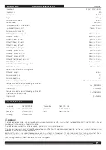
background image

PS254DB

Original instructions

Summary of Contents for PS254DB

Page 1: ...PS254DB Original instructions ...

Page 2: ...2 2 Important It is essential that you read the instructions in this manual before assembling operating and maintaining the product Subject to technical modifications ...

Page 3: ...ds zone boundary line 9 Table lock button 10 Mitre detent bypass button 11 Mitre lock lever 12 Control arm 13 Mitre scale 14 Turning table 15 Rotating extension table 16 Saw base 17 Fixed fence 18 Work clamp 19 Mounting holes x 4 20 Slide lock knob 21 Slide bar 22 Crown and baseboard setting lever 23 Crown stop 24 Baseboard lock groove 25 Dust bag 26 Upper blade guard 27 LED switch 28 Depth contro...

Page 4: ... handle 2 Head lock pin 1 Dust bag 2 End of frame assembly 3 Exhaust port Fig 5 1 Mounting holes 2 Mounting surface 3 Base PSU1000 PSUM1000 2 3 Fig 2 1 1 Depth control knob 2 Lock nut 3 Depth stop 4 Head lock pin 1 Sliding fence 2 Fence lock knob 3 Slot Fig 1 ...

Page 5: ...ork clamp 3 Work clamp hole Fig 8 Fig 9 1 Spindle lock button 2 Saw blade 3 Outer flange 4 Blade bolt 5 Arbor 6 Lower blade guard 7 Blade wrench 1 Adjustable throat plate 1 1 1 2 3 2 3 4 5 6 3 4 7 To tighten 2 5 1 Mitre detent bypass button 2 Mitre lock lever 1 2 To loosen ...

Page 6: ...base 4 Mitre lock nut 1 Sliding fence 2 Fixed fence 3 Framing square 4 Turning table 5 Mitre lock lever 6 Mitre detent bypass button 7 Saw blade 8 Screws 1 Mitre lock nut 2 Mitre lock screw 3 Mitre lock lever Underside of mitre lock lever 1 1 2 3 2 3 1 2 3 4 7 6 5 8 8 4 ...

Page 7: ...ghten 7 To loosen 1 Mitre scale 2 Scale indicator 1 Saw blade 2 Framing square 3 Turning table 4 Fixed frence 1 Saw blade 2 Framing square 3 Turning table 4 3 1 1 1 2 2 3 4 5 6 7 1 1 3 2 View of blade not square with fence adjustments are required View of blade not square with turning table adjustments are required 2 1 4 2 2 ...

Page 8: ...Bevel lock knob 4 Bevel detent lever 1 Screws 2 Bevel detent plate 3 Micro adjust screw 1 1 1 1 1 2 3 2 2 2 3 4 1 LED switch 2 Shadow of blade teeth projected onto workpiece 1 Slide lock knob 2 Work clamp Back of bevel lock bracket CROSS CUT Front of bevel lock bracket ...

Page 9: ... engaged 4 Bevel detent lever 5 Bevel lock knob 6 To tighten 7 To loosen Fig 24 Fig 25 Fig 26 1 Work clamp 1 Sliding fence 2 Rotating extension table 2 1 Table lock button 1 Work clamp 1 1 1 1 MITRE CUT EXTENDED MITRE CUT BEVEL DETENT LEVER BEVEL CUT 1 2 5 7 3 4 6 ...

Page 10: ...ece 2 Workpiece supports Fig 30 Fig 31 Fig 32 1 Compound mitre cut 1 Slide saw arm forward 2 Push down 3 Push back 1 Auxiliary fence 2 Align board with edge of mitre table 1 Wide board SLIDE CUT 45º x 45º COMPOUND MITRE CUT 1 1 2 1 1 2 1 2 3 ...

Page 11: ...JOTJEF DPSOFS s 3JHIU TJEF PVUTJEF DPSOFS 1 Fig 34 1 Sliding fence 2 Mitre table 1 3 4 Top edge against fence s FGU TJEF JOTJEF DPSOFS s 3JHIU TJEF PVUTJEF DPSOFS 2 1 Inside corner 2 Sliding fence 3 Outside corner 4 Mitre table Fig 35 1 Work clamp 2 C clamp 3 Workpiece 4 Spacer 1 2 3 1 Cut these grooves with saw 2 Use a chisel to cut out the middle 3 Workpiece ...

Page 12: ...ig 38 Fig 39 Fig 40 Fig 41 Fig 42 1 Hole A 2 Crown stop 3 Hole B 4 Crown stop lock knob 1 Slide lock knob 2 Crown and baseboard setting lever 3 Crown stop 4 Baseboard lock groove RIGHT WRONG 3 3 2 2 1 1 1 4 4 ...

Page 13: ...841 A weighted sound pressure level LpA 95 2 dB A Uncertainty K K 3 dB A Measured values determined according to EN 62841 A weighted sound power level LwA 108 1 dB A Uncertainty K K 3 dB A WARNING The declared noise emission value s have been measured in accordance with a standard test method of EN 62841 1 and EN 62841 3 9 and may be used for comparing one tool with another The declared noise valu...

Page 14: ...om frequent use of tools allow you to become complacent and ignore tool safety principles A careless action can cause severe injury within a fraction of a second POWER TOOL USE AND CARE Do not force the power tool Use the correct power tool for your application The correct power tool will do the job better and safer at the rate for which it was designed Do not use the power tool if the switch does...

Page 15: ...easing the switch before the saw head is completely in the down position The braking action of the saw may cause the saw head to be suddenly pulled downward causing a risk of injury SAFETY INSTRUCTIONS FOR WOOD CUTTING BLADE Please read the manual and instructions carefully before using the saw blade and the machine The product must be in good condition the spindle without deformation and vibratio...

Page 16: ...uum cleaner Do not replace the LED with a different type Any repairs must only be carried out by the manufacturer or authorised service agent It is recommended that the product always be supplied via a residual current device having a rated residual current of 30mA or less When using the product voltage fluctuations may affect other electrical products or lighting on the same power circuit Connect...

Page 17: ...ING MITRE FENCES See figure 2 Ŷ Turn the fence lock knob counterclockwise to clear fixed fence slots Ŷ Install the sliding mitre fence Lower fence into fence slots Be sure side of fence lines up flush with side of fixed fence Ŷ Tighten fence lock knob securely Repeat on other side USING THE DEPTH GUIDE See figure 3 When used the depth guide limits the downward travel of the blade when cutting dado...

Page 18: ...ce prior to making the cut The work clamp can be installed and used on either side of the blade To install the work clamp Ŷ Place the work clamp shaft in one of the holes located behind the sliding mitre fence Ŷ Rotate the knob on the work clamp to move it up or down as needed ADJUSTING THE MITRE LOCK See figure 9 10 Prior to squaring the saw blade to the fence ensure the mitre table moves and loc...

Page 19: ...the square as shown in figure 16 adjustments are needed TO ADJUST THE BEVEL See figures 17 18 Ŷ Remove the bevel lock dust cover Ŷ Move the bevel detent lever to the detent disengaged position Ŷ Set the bevel at any angle that allows access to the 4 screws on the back of the bevel lock bracket Ŷ Tighten the bevel lock knob Ŷ Using a 4 mm hex wrench loosen the 4 screws that hold the bevel detent pl...

Page 20: ...allow the saw blade to stop rotating before raising the blade out of workpiece and removing the workpiece from the mitre table TO MAKE EXTENDED MITRE CUTS See figure 22 24 The extended mitre capacity of the saw allows you to make mitre cuts up to 70 Using the mitre extension tables you can cut 22 5 mitres for acute 45 corners WARNING When performing 70 mitre cut only 0 bevel angle is allowed The r...

Page 21: ...l the scale indicator aligns with the desired angle on the mitre scale NOTE When performing 45 bevel compound cut the maximum mitre angle is 45 When performing 70 mitre cut only 0 bevel angle is allowed Ŷ Release the detent release button then push the mitre lock lever down to secure the mitre table Ŷ Loosen the bevel lock knob NOTE Firmly grasp the D handle while loosening the bevel lock knob to ...

Page 22: ...mitre cut as shown in figure 30 it may be necessary to adjust or remove the sliding mitre fence to ensure proper clearance prior to making the cut Make sure the fence lock knob is tightened securely to avoid interference with the saw head CLAMPING WIDE WORKPIECES See figure 32 When cutting wide workpieces such as a nominal 50 mm x 50 mm boards should be clamped securely WARNING Never make a cut by...

Page 23: ...able set left 35 3o 3 Save right end of cut 45o 30o Left Right side of outside corner 1 Top edge of molding against fence 2 Mitre table set right 35 3o 3 Save right end of cut 45o 30o Right Left side of inside corner 1 Bottom edge of molding against fence 2 Mitre table set right 35 3o 3 Save right end of cut 45o 30o Right Right side of inside corner 1 Top edge of molding against fence 2 Mitre tabl...

Page 24: ...nt injury To secure the product prior to movement Ŷ The product should be stored at the zero degree mitre and bevel angle and locked in position The slide should be locked The handle should be locked in the lower safe position with the guards closed To move or transport in a vehicle Ŷ Secure the product prior to movement as described in the manual Ŷ Remove the product from the bench top by releasi...

Page 25: ...2 mm Width of cut Arbor hole and blade size For cutting wood only 2 1 1 2 Adjust the position of sliding fence before performing bevel or compound cuts Do not dispose of electric tools together with household waste material Electric tools and electronic equipment that have reached the end of their life must be collected separately and returned to an environmentally compatible recycling facility ...

Page 26: ...26 26 ...

Page 27: ...27 27 ...

Page 28: ...www aeg pt com Techtronic Industries GmbH Max Eyth Straße 10 D 71364 Winnenden Germany ...

Reviews: