


16
16
may fall from the cutting area.
Disconnect the product from the mains supply or remove battery
pack before carrying out any maintenance or cleaning the product.
Only connect to the mains supply when the product is switched off.
Never reach into the area near the blade unless the blade has
completely stopped.
Before use, thoroughly check the product, cable and plug for any
damage or material fatigue. Repairs to the whole product should only
be carried out by an authorised service centre.
Always use the guards on the product. Do not use the product if the
guards are not in place and working correctly.
The lower blade guard should only open when the blade is lowered
to the workpiece and must always be able to move freely and close
automatically.
Always fix and use extension bar holders for workpiece support
during operation.
Never alter of modify the product or its function. Your safety may be
compromised.
Do not use saw blades which are cracked, damaged or deformed.
Do not use saw blades made of high-speed steel.
Only use blades that are sharp. Replace dull blades.
Always use blades with correct size and shape of arbor holes.
Blades that do not match the mounting hardware of the saw will run
eccentrically, causing loss of control.
Use only woodworking blades specified in this manual, which comply
with EN 847-1.
Do not use any flanges, washers and nuts to secure the saw blade
other than those supplied or indicated in the instruction manual.
It is necessary to select a saw blade which is suitable for the material
being cut. Never use the product to cut materials other than those
specified in the intended use section in this manual.
It is important to avoid overheating the blade and melting the plastic
workpiece when cutting.
It is essential to adhere to the maximum speed specified on the saw
blade, only use saw blade that are marked with a speed equal or
higher than the speed marked on the tool.
Replace the table insert when worn or damaged.
Before work, make a dummy cut without the motor turned on so the
position of the blade, operation of the guards with respect to other
machine parts, and workpiece may be checked.
When performing mitre, bevel or compound mitre cuts, adjust or
remove the sliding fence to ensure the correct clearance from the
blade.
The bracket stop must always be engaged when transporting the
product.
Keep the floor area free of loose materials, such as chips and cut-offs.
Refrain from removing any cut-offs or other parts of the workpiece
from the cutting area whilst the product is running and the saw head
is not in the rest position.
Long workpieces must be adequately supported. The working area
of the saw includes the whole extent of the workpiece. The operator
should secure this area from accidental contact from other persons or
objects which may move the workpiece during operation.
The dust produced when using the product may be harmful to health.
Use a dust suction system and wear a suitable dust protection mask.
Remove deposited dust thoroughly with a vacuum cleaner.
Do not replace the LED with a different type. Any repairs must only be
carried out by the manufacturer or authorised service agent.
It is recommended that the product always be supplied via a residual
current device having a rated residual current of 30mA or less.
When using the product, voltage fluctuations may affect other
electrical products or lighting on the same power circuit. Connect the
product to a power source with an impedance equal to 0.
299
:
to
minimize voltage fluctuations. Contact your electric power supplier for
further clarification.
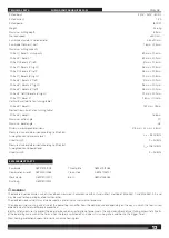
SPECIFIED CONDITIONS OF USE
The mitre saw is intended for sawing solid and bonded wood,
materials similar to wood, with or without glued veneer and plastics.
The mitre saw is intended to be used only by adult operators who
have read the instruction manual and understand the risks and
hazards.
The mitre saw is designed to be fixed at the base to a solid bench
top or a dedicated work stand. If the base is not securely fixed, the
whole machine may move during cutting operations, which increases
the possibility of serious personal injury.
The mitre saw is designed to make bevel and mitre cuts. The
capacities for the various cuts are provided in the sliding compact
mitre saw product specifications in this manual.
The mitre saw is to be used in dry conditions, with excellent ambient
lighting and adequate ventilation.
The mitre saw is intended for consumer use and should only be used
as described above and is not intended for any other purpose.
RESIDUAL RISKS
Even when the slide compound mitre saw is used as prescribed, it is
still impossible to completely eliminate certain residual risk factors.
The following hazards may arise and the operator should pay special
attention to avoid the following:
Ŷ
Risk of contact with uncovered parts of the rotating saw blade.
Ŷ
Kick-back of work pieces or parts of work pieces due to improper
adjustment or handling.
Ŷ
Catapulting of faulty carbide tips from the saw blade. Wear Eye
protection at all times.
Ŷ
Damage to the respiratory system. Wear respiratory protection
masks containing filters appropriate to the materials being
worked. Ensure adequate workplace ventilation. Do not eat, drink
or smoke in the work area.
Ŷ
Damage to hearing if effective hearing protection is not worn.
WARNING!
Dust from certain paints, coatings, and materials
may cause irritation or allergic reactions. Dust from wood such as
oak, beech, MDF, and others are carcinogenic. Materials containing
asbestos should only be worked on or processed by qualified
specialist operators.
WARNING!
Injuries may be caused or aggravated by prolonged
use of a tool. When using any tool for prolonged periods, ensure you
take regular breaks.
ASSEMBLY
UNPACKING
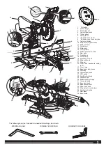
Packing list
Ŷ
Mitre saw x 1
Ŷ
Saw blade x 1
Ŷ
Dust bag x 1
Ŷ
Work clamp x 1
Ŷ
Left sliding fence x 1
Ŷ
Right sliding fence x 1
Ŷ
Operator’s manual x 1
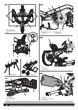
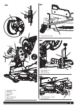
The product requires assembly.
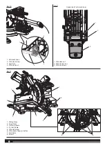
Carefully lift the saw from the carton by holding both the “D” handle
and carrying handle, and place it on a level work surface.
The product has been shipped with the saw arm secured in the down
position. To release the saw arm, push down on the top of the saw
arm, cut the tie-wrap, and pull out the head lock pin.


