


17
17
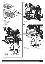
WARNING!
The saw arm is spring loaded. Hold the handle down
to prevent saw arm from snapping up when cutting the tie-wrap.
Failure to do so could result in possible serious injury.
Ŷ
Lift the saw arm by the handle. Hand pressure should remain on
the saw arm to prevent sudden rise upon release of the tie wrap.
Ŷ
Inspect the product carefully to make sure no breakage or
damage occurred during shipping.
Ŷ
Do not discard the packing material until you have carefully
inspected and satisfactorily operated the product.
Ŷ
The product is factory set for accurate cutting. After assembling
it, check for accuracy. If shipping has influenced the settings, refer
to specific procedures explained in the manual.
WARNING!
If any parts are damaged or missing, do not operate
the product until the parts are replaced. Use of the product with
damaged or missing parts could result in serious personal injury.
WARNING!
Do not attempt to modify the product or create
accessories not recommended for use with the product. Any such
alteration or modification is misuse and could result in a hazardous
condition leading to possible serious personal injury.
WARNING!
To prevent accidental starting that could cause
serious personal injury, always disconnect the product from the
mains supply or remove the battery pack(s) from the product when
assembling parts.
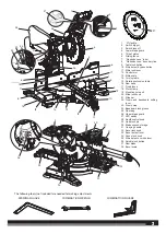
MOUNTING HOLES
See figure 1.
WARNING!
Before starting any cutting operation, mount the
product to a solid workbench. Never operate the product on the floor
or in a crouched position. Failure to heed this warning can result in
serious personal injury.
The product should be mounted to a firm supporting surface such as
a workbench, mounting board. Four bolt holes have been provided in
the saw base for this purpose. Each of the four mounting holes should
be bolted securely using 7.9 mm (5/16 in.) machine bolts, lock washers,
and hex nuts (not included). Bolts should be of sufficient length to
accommodate the saw base, lock washers, hex nuts, and the thickness
of the workbench. Tighten all four bolts securely.
The hole pattern for mounting to a workbench is shown in Figure 1.
Carefully check the workbench after mounting to make sure that no
movement can occur during use. If any tipping, sliding, or walking is
noted, secure the workbench to the floor before operating.
Mounting on a stand
The product is compatible with mitre saw stands PSU1000 and
PSUM1000 (sold separately). To mount the product on the PSU1000
or PSUM1000, use the four bolts supplied. Align the mounting holes
on the saw with the ones on the mounting brackets. Secure the saw
by tightening all bolts. For detailed mounting instructions, refer to the
user manual of respective stands.
CARRYING HANDLE
WARNING!
Use both the “D” handle and the carrying handle
to move or carry the product. Always disconnect the mains supply
before moving.
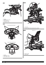
INSTALLING MITRE FENCES
See figure 2.
Ŷ
Turn the fence lock knob counterclockwise to clear fixed fence
slots.
Ŷ
Install the sliding mitre fence. Lower fence into fence slots. Be sure
side of fence lines up flush with side of fixed fence.
Ŷ
Tighten fence lock knob securely. Repeat on other side.
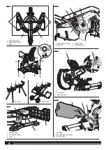
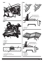
USING THE DEPTH GUIDE
See figure 3.
When used, the depth guide limits the downward travel of the blade
when cutting dadoes and other non-through cuts.
To use the depth guide:
Ŷ
Unplug the saw.
Ŷ
Rotate the depth stop outward.
Ŷ
Loosen the lock nut.
Ŷ
With the depth control knob touching the depth stop, adjust the
depth control knob by turning the knob until the desired depth
of cut is attained.
Ŷ
Tighten the lock nut.
Ŷ
A wooden spacer must be placed between the workpiece and
the fence to create a distance of 90 mm inches between the
workpiece and the fence for a consistent depth of cut in the
workpiece. Use the work clamp to clamp the spacer and another
suitable clamp to clamp the workpiece. Make the slide cut at the
desired depth. See Figures 34 and 35.
Ŷ
Rotate the depth stop inward for normal through cuts.
NOTE:
The depth stop must be pushed in before locking/unlocking
the saw arm.
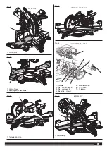
LOCKING/UNLOCKING THE SAW ARM
See figure 4.
When locking and unlocking the saw arm, it is not necessary to loosen
the depth control knob. However, the depth stop must be pushed in.
To unlock and raise the saw arm:
Ŷ
Firmly grasp the “D” handle and apply downward pressure while
at the same time pulling the head lock pin out and away from the
saw housing.
Ŷ
Release the head lock pin and slowly raise the saw arm.
To lock the saw arm:
Ŷ
Firmly grasp the “D” handle and apply downward pressure until
head stops. Push in the head lock pin toward the saw.
Ŷ
Release the head lock pin allowing it to lock the saw into place.
NOTE
: Do not use saw to cut while in the locked position.
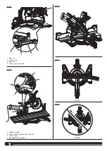
DUST BAG AND FRAME ASSEMBLY
See figure 5.
To install the dust bag and frame assembly, slide the open end of the
frame assembly onto the exhaust port.
For efficient operation, empty the dust bag before it is half full. This
will permit better air flow through the bag.
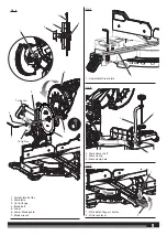
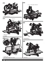
INSTALLING/REPLACING THE BLADE
See figure 6.
WARNING!
Before removing and fitting the blade, make sure to
wear safety gloves.
WARNING!
A 254 mm (10 in.) blade is the maximum blade
capacity of the product. Never use a blade that is too thick to allow
outer flange to engage with the flats on the spindle. Larger blades
will come in contact with the blade guards, while thicker blades will
prevent the blade bolt from securing the blade on the spindle. Either
of these situations could result in a serious accident and can cause
serious personal injury.
WARNING!
Only use the blade specified in this manual and its
speed is at least equal to the speed marked on the product.
Ŷ
Unplug the saw.
Ŷ
Raise the saw arm.
Ŷ
Rotate the lower blade guard to expose the blade bolt.
Ŷ
Depress the spindle lock button and rotate the blade bolt until
the spindle locks.
Ŷ
Using the hex end of the blade wrench, loosen and remove the
blade bolt from the arbor.


