


18
18
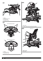
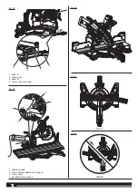
NOTE
: The blade bolt has left hand threads. Turn blade bolt
clockwise to loosen.
Ŷ
Remove the outer blade washer.
NOTE
: The inner blade washer is integrated into the spindle and
cannot be removed.
Ŷ
Wipe a drop of oil onto inner blade washer and outer blade
washer where they contact the blade.
Ŷ
Rotate the lower blade guard to expose the arbor.
Ŷ
Fit saw blade inside blade guard and onto the arbor and against
the inner blade washer. The blade teeth point downward at the
front of saw as shown.
Ŷ
Replace the outer blade washer. The double “D” flats on the blade
washers align with the flats on the spindle.
Ŷ
Depress spindle lock button and replace blade bolt.
NOTE:
The blade bolt has left hand threads. Turn blade bolt
counterclockwise to tighten.
WARNING!
Always install the blade with the blade teeth and the
arrow printed on the side of the blade pointing down at the front of
the saw. The direction of blade rotation is also stamped with an arrow
on the upper blade guard.
Ŷ
Tighten the blade bolt securely.
Ŷ
Lower the blade guard.
Ŷ
Raise and lower the saw arm to ensure the lower blade guard
functions correctly.
WARNING!
Make sure the spindle lock button is not engaged
before reconnecting saw into power source. Never engage spindle
lock button when blade is rotating.
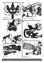
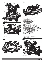
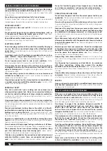
REMOVING/REPLACING THE ADJUSTABLE THROAT PLATES
See figures 7.
When squaring the saw blade, it may be necessary to move the
throat plate away from the blade. Once the saw’s alignment has
been confirmed, return the throat plate to its original position. Never
operate the saw without a throat plate installed.
Ŷ
Unplug the saw.
Ŷ
Using the blade wrench provided, loosen the screws securing the
right side of the adjustable throat plate.
NOTE
: The throat plate may be adjusted to (near) zero clearance
to support thin materials.
Ŷ
Slide the throat plate away from the blade as far as possible.
Ŷ
Retighten the screws, being careful not to overtighten which can
cause the throat plate to bow or bend.
Ŷ
Repeat the above steps for the left side of the throat plate.
Ŷ
Visually inspect and make sure that the throat plates fit flush with
the tuning table.
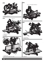
INSTALLING THE WORK CLAMP
See figure 8.
WARNING!
In some operations, the work clamp assembly may
interfere with the operation of the blade guard assembly. Always make
sure there is no interference with the blade guard prior to beginning
any cutting operation to reduce the risk of serious personal injury.
The work clamp provides greater control by clamping the workpiece
to the mitre table. It also helps to prevent the workpiece from creeping
toward the saw blade. This is helpful when cutting compound mitres.
Depending on the cutting operation and the size of the workpiece,
it may be necessary to use a C-clamp instead of the work clamp to
secure the workpiece prior to making the cut. The work clamp can be
installed and used on either side of the blade.
To install the work clamp:
Ŷ
Place the work clamp shaft in one of the holes located behind the
sliding mitre fence.
Ŷ
Rotate the knob on the work clamp to move it up or down as
needed.
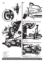
ADJUSTING THE
MITRE
LOCK
See figure 9 - 10.
Prior to squaring the saw blade to the fence, ensure the mitre table
moves and locks securely.
Ŷ
Unplug the saw.
Ŷ
Locate the mitre lock nut, mitre lock screw and mitre lock shoe on
the rear underside of the saw.
To check the clamping force of the mitre lock:
Ŷ
Unplug the saw.
Ŷ
Lift the mitre lock lever and press the mitre detent bypass button
to unlock the mitre table.
Ŷ
Rotate the mitre table to an “unindexed” mitre position other than
0˚, 15˚, 22.5˚, 31.6˚, 45˚, 60˚, and 67.5˚.
Ŷ
Push the mitre lock lever down and attempt to move the mitre
table. If the table moves easily when in the “locked” position,
adjust the mitre lock screw.
Ŷ
Using a 4 mm hex key, adjust the mitre lock screw. Make
adjustments of one-quarter turn or less.
NOTE:
Turning the mitre lock screw clockwise will increase the
clamping force. Turning the mitre lock screw counterclockwise
decreases the clamping force.
Ŷ
After making the adjustment, test the clamping force.
To adjust mitre table movement:
Ŷ
Lift the mitre lock lever, press the mitre detent bypass button, and
move the mitre table left to right. If the mitre table does not move
freely, adjust the mitre lock nut.
Ŷ
Using the 4 mm hex key, hold the mitre lock screw stationary and
use the 13 mm combination wrench to adjust the nut holding the
mitre lock shoe.
NOTE:
Turning the mitre lock nut clockwise will move the shoe
closer to the mitre saw base and make it harder to move the mitre
table. Turning the mitre lock nut counterclockwise will move the
shoe farther away from the base and make it easier to move the
table.
Ŷ
Adjust the mitre lock nut until the shoe and mitre saw base are
close but not in contact with each other.
Ŷ
After making the adjustment, test the movement of the mitre
table.
Ŷ
Rotate the mitre table to an “unindexed” mitre position other than
0˚, 15˚, 22.5˚, 31.6˚, 45˚, 60˚, and 67.5˚ and push the mitre lock
lever down. Test the clamping force.
NOTE:
It should take considerable force to move the table in the
locked position.
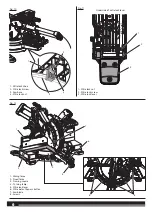
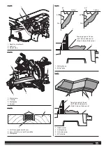
ADJUSTING THE MITRE LOCK LEVER
See figure 11.
Ŷ
Unplug the saw.
Ŷ
Lift the mitre lock lever to unlock the mitre table.
Ŷ
If the mitre lock lever is not parallel with the top of the mitre table,
adjustments are needed.
Ŷ
Using a 10 mm combination wrench and a flat head screwdriver,
hold the mitre lock screw in place and loosen the mitre lock nut.
Ŷ
Turn the mitre lock screw clockwise to lower the lever.
Ŷ
Turn the mitre lock screw counterclockwise to raise the lever.
Ŷ
Continue to adjust the lock lever until it is parallel with the mitre
table.
Ŷ
Hold the screw in place and tighten the lock nut securely.
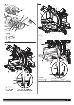
SQUARING THE SAW BLADE TO THE FENCE
See figures 12 - 15.
Ŷ
Disconnect the mains supply from the product.


