


19
19
Ŷ
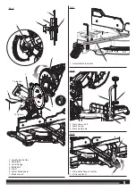
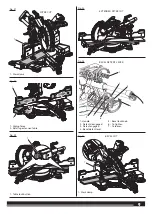
Pull the saw arm all the way down and lock in transport position.
Ŷ
Loosen the bevel lock knob and disengage the bevel detent lever.
Ŷ
Set the saw at the 0º bevel angle, engage the bevel detent lever,
and ensure the saw engages the detent.
Ŷ
Tighten the bevel lock knob.
Ŷ
Lift the mitre lock lever to unlock the mitre table.
Ŷ
Press the mitre detent button and rotate the mitre table until the
pointer on the mitre scale is positioned at 0°.
Ŷ
Release the mitre detent button and allow the mitre table to
engage the 0° detent position.
Ŷ
Push the mitre lock lever down to lock the mitre table.
Ŷ
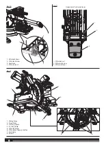
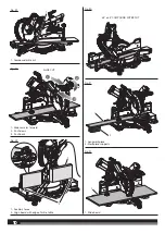
Lay a framing square flat on the mitre table. Place one leg of the
square against the fixed fence. Slide the other leg of the square
against the flat part of the saw blade.
NOTE:
Make sure that the square contacts the flat part of the saw
blade, not the blade teeth.
Ŷ
The edge of the square and the saw blade should be parallel.
Ŷ
If the front or back edge of the saw blade angles away from the
square as shown in figure 14, adjustments are needed.
Ŷ
Rotate the extension tables to their fully extended position. See
“To Make Extended Mitre Cuts” later in this manual.
Ŷ
Lift the mitre lock lever to unlock the mitre table.
Ŷ
Press the mitre detent bypass button. Rotate the mitre table until
the pointer is at the left 15° position on the mitre scale.
Ŷ
Using a 4 mm hex key, loosen the 5 screws that hold the mitre
scale/detent plate in place.
Ŷ
Rotate the mitre table to the 0° position on the mitre scale and
detent engages in the detent plate.
Ŷ
Rotate the mitre table until the blade is parallel with the framing
square.
Ŷ
Push the mitre lock lever down to lock the mitre table.
Ŷ
Tighten the 4 visible screws that secure the mitre scale/detent
plate.
Ŷ
Lift the mitre lock lever to unlock the mitre table.
Ŷ
Press the mitre detent bypass button. Rotate the mitre table until
the pointer is at the left 15° position on the mitre scale.
Ŷ
Tighten the remaining screw to secure the mitre scale/detent
plate.
SQUARING THE BLADE TO THE MITRE TABLE
See figures 16.
Ŷ
Unplug the saw.
Ŷ
Pull the saw arm all the way down and lock in transport position.
Ŷ
Lift the mitre lock lever to unlock the mitre table.
Ŷ
Press the mitre detent bypass half way and rotate the mitre table
until the pointer on the mitre scale is positioned at 0°.
Ŷ
Release the mitre detent bypass and allow the mitre table to
engage the 0° detent position.
Ŷ
Push the mitre lock lever down to lock the mitre table.
Ŷ
Loosen the bevel lock knob and disengage the bevel detent lever.
Ŷ
Set the saw at the 0º bevel angle, engage the bevel detent lever
and ensure the saw engages the detent.
Ŷ
Tighten the bevel lock knob.
Ŷ
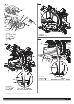
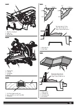
Place a combination square against the mitre table and the flat
part of the saw blade.
NOTE:
Make sure that the square contacts the flat part of the saw
blade, not the blade teeth.
Ŷ
Rotate the blade by hand and check the blade-to-table alignment
at several points.
Ŷ
The edge of the square and the saw blade should be parallel.
Ŷ
If the top or bottom of the saw blade angles away from the square
as shown in figure 16, adjustments are needed.
TO ADJUST THE BEVEL
See figures 17 - 18.
Ŷ
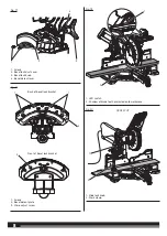
Remove the bevel lock dust cover.
Ŷ
Move the bevel detent lever to the detent disengaged position.
Ŷ
Set the bevel at any angle that allows access to the 4 screws on
the back of the bevel lock bracket.
Ŷ
Tighten the bevel lock knob.
Ŷ
Using a 4 mm hex wrench, loosen the 4 screws that hold the bevel
detent plate in place. Do not remove the screws.
Ŷ
Loosen the bevel lock knob and move the bevel detent lever to
the detent disengaged position.
Ŷ
Set the bevel angle at 0°.
Ŷ
Move the bevel detent lever to the detent engaged position.
Ŷ
Check the 0° angle using a combination square.
Ŷ
If adjustment is needed, use a 4 mm hex key to turn the micro
adjust screw on the front of the bevel lock bracket to adjust the
saw to the 0° bevel angle.
Ŷ
Tighten the bevel lock knob.
Ŷ
Tighten the 2 outermost screws that retain the bevel detent plate.
Ŷ
Loosen the bevel lock knob and set the bevel at any angle that
allows access to the 2 remaining screws on the back of the bevel
lock bracket.
Ŷ
Tighten the bevel lock knob.
Ŷ
Tighten the remaining 2 screws that retain the bevel detent plate.
Ŷ
Replace the bevel lock dust cover and tighten the screws securely.
OPERATION
WARNING!
Do not allow familiarity with products to make you
careless. Remember that a careless fraction of a second is sufficient
to inflict severe injury.
WARNING!
Always wear eye protection with side shields. Failure
to do so could result in objects being thrown into your eyes, resulting
in possible serious injury.
WARNING!
Do not use any attachments or accessories not
recommended by the manufacturer of the product. The use of
attachments or accessories not recommended can result in serious
personal injury.
WARNING!
To avoid serious personal injury, always push the
mitre lock lever down and tighten the bevel lock knob securely before
making a cut. Failure to do so could result in movement of the control
arm or mitre table while making a cut.
WARNING!
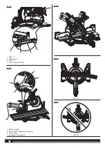
To avoid serious personal injury, keep your hands
outside the no hands zone, at least 100 mm from blade. Never
perform any cutting operation freehand (without holding workpiece
against the fence). The blade could grab the workpiece if it slips or
twists.
WARNING!
Before starting any cutting operation, clamp or bolt
your mitre saw to a workbench or leg stand. Never operate your mitre
saw on the floor or in a crouched position. Failure to heed this warning
can result in serious personal injury.
WARNING!
Do not start your compound mitre saw without
checking for interference between the blade and the mitre fence.
Damage could result to the blade if it strikes the mitre fence during
operation of the saw. Failure to heed this warning can also result in
serious personal injury.
CUTTING WITH YOUR SLIDING COMPOUND MITRE SAW
WARNING!
When using a work clamp or C-clamp to secure
your workpiece, clamp workpiece on one side of the blade only. The
workpiece must remain free on one side of the blade to prevent the
blade from binding in workpiece. The workpiece binding the blade
will cause motor stalling and kickback. This situation could cause an
accident resulting in possible serious personal injury.
WARNING!
Never move the workpiece or make adjustment to


