


21
21
Ŷ
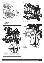
Loosen the bevel lock knob.
NOTE
: Firmly grasp the “D” handle while loosening the bevel lock
knob to prevent the saw head from shifting unexpectedly.
Ŷ
Move the bevel detent lever to the detent engaged position to
select one of the preset bevel settings or place the bevel detent
lever in the detent disengaged position to select any desired
setting.
NOTE
: Indexed bevel positions are located at 0°, 15°, 22.5°, 33.9°,
and 45° left or right.
Ŷ
Tighten the bevel lock knob.
Ŷ
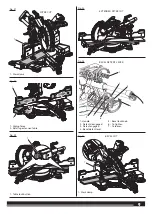
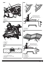
Place the workpiece flat on the mitre table with one edge securely
against the fence. If the board is warped, place the convex side
against the fence. If the concave edge of a board is placed against
the fence, the board could collapse on the blade at the end of the
cut, jamming the blade. See Figures 41 - 42.
Ŷ
When cutting long pieces of lumber or molding, support the
opposite end of the workpiece with a roller stand or with a work
surface level with the saw table. See Figure 31.
Ŷ
Grasp the workpiece firmly with one hand and secure it against
the fence. Use the work clamp or a C-clamp to secure the
workpiece when possible.
Ŷ
Before turning on the saw, perform a dry run of the cutting
operation to make sure that no problems will occur when the cut
is made.
Ŷ
Align cutting line on the workpiece with the edge of saw blade.
Ŷ
Turn the LED switch on to project the blade shadow onto the
workpiece.
Ŷ
Grasp the saw handle firmly. Turn on the saw and allow several
seconds for the blade to reach maximum speed.
Ŷ
Slowly lower the blade into and through the workpiece.
Ŷ
Release the switch trigger and allow the saw blade to stop rotating
before raising the blade out of the workpiece and removing the
workpiece from the mitre table.
TO COMPOUND MITRE CUT
See figure 27.
A compound mitre cut is a cut made using a mitre angle and a bevel
angle at the same time. This type of cut is used to make picture
frames, cut molding, make boxes with sloping sides, and for certain
roof framing cuts.
To make this type of cut the control arm on the mitre table must
be rotated to the correct angle and the saw arm must be tilted to
the correct bevel angle. Care should always be taken when making
compound mitre setups due to the interaction of the two angle
settings.
Adjustments of mitre and bevel settings are interdependent with one
another. Each time you adjust the mitre setting you change the effect
of the bevel setting. Also, each time you adjust the bevel setting you
change the effect of the mitre setting.
It may take several settings to obtain the desired cut. The first angle
setting should be checked after setting the second angle, since
adjusting the second angle affects the first.
Once the two correct settings for a particular cut have been obtained,
always make a test cut in scrap material before making a finish cut in
good material.
NOTE
: It may be necessary to adjust or remove the sliding mitre
fence to insure proper clearance prior to making the cut. Make sure
the fence lock knob is tightened securely to avoid interference with
the saw head.
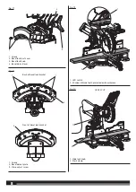
Ŷ
Slide the saw head to its most rearward position and tighten the
slide lock knob securely.
Ŷ
Pull out the lock pin and lift saw arm to its full height.
Ŷ
Lift the mitre lock lever and depress the detent release button to
release the mitre table.
Ŷ
Rotate the control arm until the scale indicator aligns with the
desired angle on the mitre scale.
NOTE
: When performing 45° bevel compound cut, the maximum
mitre angle is 45°. When performing 70° mitre cut, only 0° bevel
angle is allowed.
Ŷ
Release the detent release button, then push the mitre lock lever
down to secure the mitre table.
Ŷ
Loosen the bevel lock knob.
NOTE
: Firmly grasp the “D” handle while loosening the bevel lock
knob to prevent the saw head from shifting unexpectedly.
Ŷ
Move the bevel detent lever to the detent engaged position to
select one of the preset bevel settings or place the bevel detent
lever in the detent disengaged position to select any desired
setting.
NOTE
: Indexed bevel positions are located at 0°, 15°, 22.5°, 33.9°,
and 45° left or right.
Ŷ
Tighten the bevel lock knob.
Ŷ
Recheck mitre angle setting. Make a test cut in scrap material.
Ŷ
Place the workpiece flat on the mitre table with one edge securely
against the fence. If the board is warped, place the convex side
against the fence. If the concave edge of a board is placed against
the fence, the board could collapse on the blade at the end of the
cut, jamming the blade. See Figures 41 - 42.
Ŷ
When cutting long pieces of lumber or molding, support the
opposite end of the workpiece with a roller stand or with a work
surface level with the saw table. See Figure 31.
Ŷ
Grasp the workpiece firmly with one hand and secure it against
the fence. Use the work clamp or a C-clamp to secure the
workpiece when possible.
Ŷ
Before turning on the saw, perform a dry run of the cutting
operation to make sure that no problems will occur when the cut
is made.
Ŷ
Align cutting line on the workpiece with the edge of saw blade.
Ŷ
Turn the LED switch on to project the blade shadow onto the
workpiece.
Ŷ
Make a test cut in scrap material.
Ŷ
Grasp the saw handle firmly. Turn the saw on and allow several
seconds for the blade to reach maximum speed.
Ŷ
Slowly lower the blade into and through the workpiece.
Ŷ
Release the switch trigger and allow the saw blade to stop
rotating before raising the blade out of workpiece and removing
the workpiece from the mitre table.
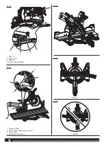
WARNING!
Never make a cut by pulling the saw toward you as
the blade can climb on top of the workpiece and come toward you.
Failure to heed this warning could result in serious personal injury.
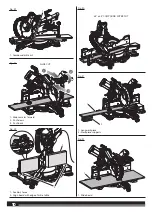
TO SLIDE CUT
See figure 28.
The sliding feature will cut nominal workpieces 305 mm wide by 38
mm thick or 152 mm wide by 89 mm thick.
With the saw off, pull the saw arm forward. Turn the saw on (let
blade reach maximum speed), push the blade down cutting into the
workpiece then back toward the rear of the saw to make a cut. Cuts
are made by pushing the saw blade away from you and toward the
bevel scale at the back of the saw stopping when the full rear position
has been reached after each cut. When the saw is running (turned on),
Never pull the saw blade toward you or toward the front of the saw.
Ŷ
Pull out the head lock pin and lift saw arm to its full height.
Ŷ
Place the workpiece flat on the mitre table with one edge securely
against the fence. If the board is warped, place the convex side
against the fence. If the concave edge of a board is placed against
the fence, the board could collapse on the blade at the end of the
cut, jamming the blade. See Figures 41 - 42.
Ŷ
When cutting long pieces of lumber or molding, support the
opposite end of the workpiece with a roller stand or with a work
surface level with the saw table. See Figure 31.
Ŷ
Align the cutting line on the workpiece with the edge of saw blade.


