


22
22
Ŷ
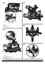
Turn the LED switch on to project the blade shadow onto the
workpiece.
Ŷ
Loosen the slide lock knob by turning the knob counterclockwise.
Ŷ
Grasp the workpiece firmly with one hand and secure it against
the fence. Use the work clamp or a C-clamp to secure the
workpiece when possible.
Ŷ
Before turning on the saw, perform a dry run of the cutting
operation to make sure that no problems will occur when the cut
is made.
Ŷ
With the saw off, grasp the saw handle firmly then pull the saw
forward until the blade arbor (center of the saw blade) is over the
front of the workpiece.
Ŷ
Turn the saw on and allow several seconds for the blade to reach
maximum speed.
Ŷ
Slowly lower the blade into and through the front edge of the
workpiece.
Ŷ
Push the saw handle away from you and toward the bevel scale
at the back of the saw.
Ŷ
Release the switch trigger and allow the saw blade to stop
rotating before raising the blade out of workpiece and removing
the workpiece from mitre table.
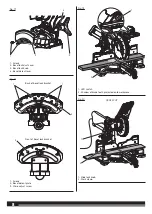
MAKING AN AUXILIARY FENCE
See figure 29.
Depending on the size and position of the workpiece, certain unusual
cuts may benefit from the additional support that can be provided
by an auxiliary fence. The holes provided in the mitre fence are used
to secure an auxiliary fence in place. To make an auxiliary fence, we
recommend using two pieces of wood 10 mm thick, 90 mm. high, and
250 mm. long.
NOTE
: The auxiliary fence can only be used when the bevel is set at
0°. When making a bevel cut, the auxiliary fence must be removed.
To attach the auxiliary fence to the saw:
Ŷ
Make sure the fence lock knob is tightened securely.
Ŷ
Place the 250 mm. long piece of wood against the mitre fence and
aligned with the left edge of the mitre table.
Ŷ
Clamp the wood tightly against the fence and drive wood screws
from the back of the fence through the two holes and into the
auxiliary fence. If necessary, drill a pilot hole into wood first to
prevent splitting. Remove clamp when finished.
NOTE
: Make sure the screws you use to attach the auxiliary fence
do not pass through the front face of the fence and the length of
the screws will not put them in the path of the blade at any angle.
Ŷ
Make full 45° left and right mitre cuts through the auxiliary fence.
NOTE
: Check for interference between the auxiliary fence and the
lower blade guard. Correct any interference before proceeding.
Ŷ
Repeat steps with second board by aligning with right side of
mitre table.
WARNING!
Both sides of the auxiliary fence must be aligned on
the same plane.
WARNING!
When using an auxiliary fence, check and ensure that
there is no interference with any part of the saw during operation.
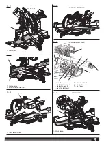
SUPPORTING LONG WORKPIECES
See figure 30 - 31.
Long workpieces need extra support. Supports should be placed
along the workpiece so it does not sag. The support should let the
workpiece lay flat on the base of the saw and mitre table during the
cutting operation. Use the work clamp or a C-clamp to secure the
workpiece.
NOTE:
When making a compound mitre cut as shown in figure 30,
it may be necessary to adjust or remove the sliding mitre fence to
ensure proper clearance prior to making the cut. Make sure the fence
lock knob is tightened securely to avoid interference with the saw
head.
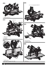
CLAMPING WIDE WORKPIECES
See figure 32.
When cutting wide workpieces, such as a nominal 50 mm. x 50 mm,
boards should be clamped securely.
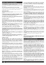
WARNING!
Never make a cut by pulling the saw toward you as
the blade can climb on top of the workpiece and come toward you.
Failure to heed this warning could result in serious personal injury.
ROUGH CUTTING A DADO
See figure 33 - 35.
Using a wood chisel and the depth control knob, it is possible to make
a rough dado cut. Always make a practice cut on scrap wood.
To use the depth control knob:
Ŷ
Unplug the saw.
Ŷ
Rotate the depth stop outward.
Ŷ
Loosen the lock nut.
Ŷ
With the depth control knob touching the depth stop, adjust the
depth control knob by turning the knob until the desired depth
of cut is attained.
Ŷ
Tighten the lock nut.
Ŷ
A wooden spacer must be placed between the workpiece and the
fence to create a distance of 3-1/2 inches between the workpiece
and the fence for a consistent depth of cut in the workpiece. Use
the work clamp to clamp the spacer and another suitable clamp
to clamp the workpiece. Make the slide cut at the desired depth.
Ŷ
Rotate the depth stop inward for normal through cuts.
NOTE
: The depth stop must be pushed in before locking/
unlocking the saw arm.
To make the cut:
Ŷ
Unlock the slide lock knob.
Ŷ
Pull out the head lock pin and lift saw arm to its full height.
Ŷ
With the saw off, pull the saw arm forward. Turn the saw on (let
blade reach maximum speed), then push the blade down on top
of the workpiece then back toward the rear of the saw to make
a cut.
Ŷ
Cut two outside grooves in the workpiece.
Ŷ
Using a wood chisel, remove the material between the two
outside grooves.
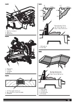
CUTTING CROWN MOLDING
The compound mitre saw does an excellent job of cutting crown
molding. In general, compound mitre saws do a better job of cutting
crown molding than any other tool.
In order to fit properly, crown molding must be compound mitred with
extreme accuracy.
The two contact surfaces on a piece of crown molding that fit flat
against the ceiling and the wall of a room are at angles that, when
added together, equal exactly 90°. Most crown molding has a top rear
angle (the section that fits flat against the ceiling) of 52° and a bottom
rear angle (the section that fits flat against the wall) of 38°.
LAYING MOLDING FLAT ON THE MITRE TABLE
See figure 36 - 37.
To use this method for accurately cutting crown molding for a 90°
inside or outside corner, lay the molding with its broad back surface
flat on the mitre table and against the fence.
When setting the bevel and mitre angles for compound mitres,
remember that the settings are interdependent; changing one angle
changes the other angle as well.
Keep in mind that the angles for crown molding are very precise
and difficult to set. Since it is very easy for these angles to shift, all
settings should first be tested on scrap molding. Also most walls do
not have angles of exactly 90°; therefore, you will need to fine tune
your settings.


