


24
24
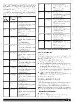
NOTE
: This lever position is for left and right mitre cuts up to 45°
Ŷ
Push the saw head all the way toward the rear of the saw until the
saw head stops and tighten the slide lock knob.
Ŷ
Perform a dry run prior to making any cut after repositioning the
sliding mitre fences to ensure there is no interference.
Ŷ
To disengage the crown setting lever, unlock the slide lock knob,
push the crown and baseboard setting lever in.
To position for vertical base molding:
Ŷ
Unplug the saw.
Ŷ
Loosen the slide lock knob and push the saw away from you and
toward the rear of the saw.
Ŷ
Flip the crown and baseboard setting lever up while pulling the
saw head toward the front of the saw until the baseboard lock
groove engages.
NOTE
: This lever position is for cuts between 45° left and 45°
right.
Ŷ
Tighten the slide lock knob securely.
Ŷ
Perform a dry run prior to making any cut after repositioning the
sliding mitre fences to ensure there is no interference.
Ŷ
To disengage the baseboard setting lever, unlock the slide lock
knob, push the crown and baseboard setting lever in.
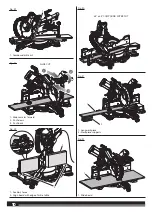
CUTTING BASE MOLDING
See figure 40.
Ŷ
Set the mitre angle at 0° and the bevel angle at 45° to either the
left or the right. (For making 90° corners.)
Ŷ
Place and secure the base molding flat against the fence using
the work clamp and hold the base molding securely.
Ŷ
Before turning on the saw, perform a dry run of the cutting
operation to make sure that no problems will occur when the cut
is made.
Ŷ
Grasp the saw handle firmly. Squeeze the switch trigger. Allow
several seconds for the blade to reach maximum speed.
Ŷ
Slowly lower the blade into and through the base molding.
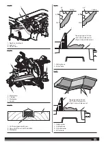
CUTTING WARPED MATERIAL
See figures 41 - 42.
When cutting warped material, always make sure it is positioned on
the mitre table with the convex side against the fence as shown in
figure 41.
If the warped material is positioned the wrong way as shown in figure
42, it will pinch the blade near the completion of the cut.
WARNING!
To avoid kickback and to avoid serious personal
injury, never position the concave edge of bowed or warped material
against the fence.
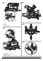
TRANSPORTATION AND STORAGE
When storing the product, disconnect the mains supply. Store the
product in a secure place that is not accessible to children.
Clean the product using a brush and vacuum cleaner before storage.
If you remove the saw blade or keep spares with the unit, ensure they
are in the original packaging to prevent injury.
To secure the product prior to movement:
Ŷ
The product should be stored at the zero degree mitre and
bevel angle and locked in position. The slide should be locked.
The handle should be locked in the lower (safe) position with the
guards closed.
To move or transport in a vehicle:
Ŷ
Secure the product prior to movement as described in the manual.
Ŷ
Remove the product from the bench top by releasing the 4 bolts,
one at each corner. Secure the bolts for future use.
Ŷ
When lifting to a height, carry the product by holding both the “D“
handle and carrying handle.
Ŷ
When transporting in a vehicle, set the product on its base and
secure against movement.
MAINTENANCE
Do not modify this saw in any way or use accessories not approved by
the manufacturer. Your safety and that of others may be compromised.
Do not use the saw if any switches, guards or other function of this
saw does not work as it is intended to. Return to an authorised service
centre for professional repair or adjustment.
Do not make any adjustments whilst the saw blade is in motion.
Disconnect the mains supply before making adjustments, lubricating
or when doing any maintenance on the machine.
Before and after each use, check your saw for damage or broken parts
and keep it in top working condition by replacing parts immediately
with spares approved by the manufacturer.
The blade is very hot after use, wear gloves or allow to cool before
maintenance or cleaning procedures.
Clean out accumulated dust using a brush or vacuum cleaner. Do not
use compressed air.
If the power cord is damaged, it must be replaced by an authorised
service centre in order to avoid a safety hazard.
To assure safety and reliability, all repairs, including changing brushes,
should be performed by an authorised service centre.
WARNING!
For greater safety and reliability, all repairs should be
performed by an authorised AEG service centre.
Use only AEG accessories and spare parts. Should components need
to be replaced which have not been described, please contact one of
our AEG service agents (see our list of guarantee/service addresses).
If needed, an exploded view of the product can be ordered. Please
state the Article No. as well as the machine type printed on the label
and order the drawing at your local service agents or directly at:
Techtronic Industries GmbH
Max-Eyth-Straße 10,
D-71364 Winnenden,
Germany.
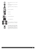
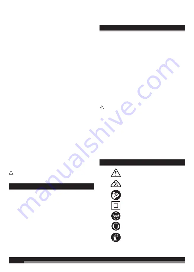
SYMBOLS
Safety alert
Regulatory Compliance Mark (RCM).
Product meets applicable regulatory
requirements.
Please read the instructions carefully
before starting the machine.
Class II tool, double insulation
Always wear goggles when using the
machine.
Wear ear protectors.
Wear gloves


