

3
3
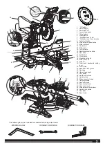
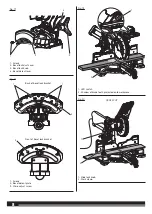
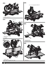
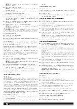
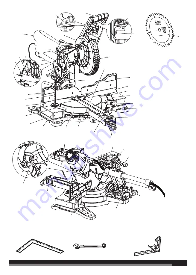
The following tools (not included) are needed for making adjustments:
COMBINATION SQUARE
COMBINATION WRENCH
FRAMING SQUARE
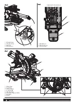
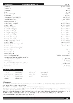
Ø 254 mm
n
max.
7000
Ø 30 mm
48 HW
2.2 mm
25
26
4
5
13
10
11
14
16
6
18
21
12
1
8
7
8
9
15
6
22
20
24
23
38
17
19
17
2
3
37
32
34
31
29
30
28
2
33
35
36
27
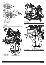
1. “D”
Handle
2. Switch
trigger
3. Switch lock off
4. Lower blade guard
5. Throat
plates
6. Sliding
fence
7. “No hands zone” label
8. “No hands zone” boundary line
9. Table lock button
10. Mitre detent bypass button
11. Mitre lock lever
12. Control arm
13. Mitre scale
14. Turning table
15. Rotating extension table
16. Saw base
17. Fixed fence
18. Work clamp
19. Mounting holes x 4
20. Slide lock knob
21. Slide bar
22. Crown and baseboard setting
lever
23. Crown stop
24. Baseboard lock groove
25. Dust bag
26. Upper blade guard
27. LED switch
28. Depth control knob
29. Head lock pin
30. Blade wrench storage
31. Carrying handle
32. Bevel lock knob
33. Bevel detent lever
34. Fence lock knob
35. Mitre detent override lever
36. Spindle lock button
37. Saw blade
38. Bevel scale


