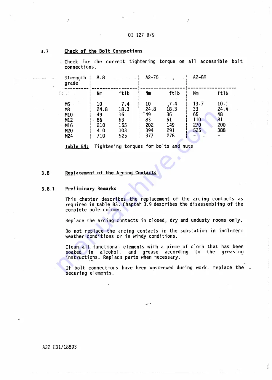
Check
for
the
corre:t
tightening
torque
on all
accessible
bolt
connections.
5
t
Y'f.'ngth
I
8.8
.A2-70
!
A2-80
I
.
grade
I
I
I
~
.'---'_.----
--------.,.-··:------1-----------------:
--------------.~-~-
Nm
··:tlb
I
Nm
ftlb
I
Nm
ftlb
I
I
I
I
i
I
M6
10
7.4
I
10
).4
I
13.7
10 .1
I
I
M8
24.8
:.8.3
I
24.8
18.3
I
33
24.4
I
I
MIO
49
]6
: -""49
36
I
65
48
I
M12
86
li3
I
83
61
I
110
81
I
I
M16
210
:.55
I
202
149
I
270
200
I
I
M20
410
]03
I
394
291
I
525
388
I
I
M24
710
!i25
I
377
278
I
I
I
Table
84:
Tighteninq
torques
for
bolts
and nuts
This
chapter
descril:es
the
replacement
of
the
arcing
contacts
as
required
in table
83. Chapter
3.9 describes
the disassembling
of the
complete
pole
column.
Replace
the
arcing
CJntacts
in closed,
dry and undusty
rooms only.
Do not
replace
the
I:rcing
contacts
in the
substation
in
inclement
weather
conditions
or in windy conditions.
Cl ean
all
funct i ona'l
elements
with
a pi ece of cloth
that
has
been
soaked
in
a 1coho 1.
and
grease
accord i ng
to
the
greas i ng
instructi.<:ns.
Replac~
parts
when necessary.
If
bolt
connections
have
been
unscrewed
during
work,
replace
the
securing
elements.
Summary of Contents for SF6
Page 21: ...Fig 83 Exploded view of tle spring operating mechanism ...
Page 31: ...SF 1377 0 SF 1377 d SF 1377 0 SF 1377 0 SF 1377 _ 0 SF 1377 d SF 1377 0 SF 1377 0 ...
Page 32: ...SF 1377 c rUlUb m m I SF 1377 c J i SF 1377 SF 137 b 0 SF 1377 SF 1377 0 b ...
Page 33: ...BeruLub FK 33 Fig B8 Points of lubrication at the interrupter unit and at thE arcing contacts ...
Page 34: ...SF 1377 bl SF 1377 bl SF 1377 II 1 _ _ _ __ L i SF 1377 bl SF 1377 cl SF 1377 bl SF 1377 bl ...
Page 35: ...1 CLtl _ l1oLykote BR2 pLus l 0 ...
Page 38: ...2 7 17 2 7 18 2 7 16 2 7 02 2 7 18 2 7 03 2 7 01 2 7 06 2 7 11 2 7 07 2 7 22 ...


