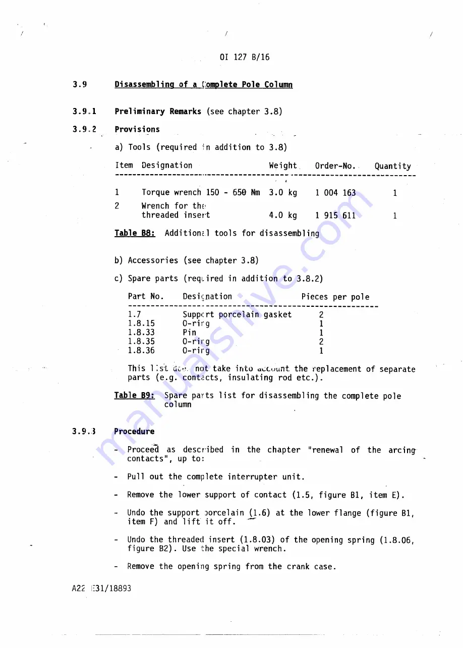
Torque wrench 150 - 650 Nm
3.0 kg
Wrench for thE~
threaded insert
4.0 kg
b) Accessories
(see chapter 3.8)
c) Spare parts (reqLired in addition to 3.8.2)
1.7
1.8.15
1.8.33
1.8.35
1.8.36
Suppcrt porcelain gasket
O-rirg
Pin
O-rirg
O-rirg
This 1 :s:t.
de•.
·. not take into
a~c.uunt
the replacement of separate
parts (e.g. contacts, insulating rod etc.).
Table
89:
Spare parts list for disassembling
the complete pole
column
Procedure
Proceed
as descri bed
in the
chapter
II
renewa 1 of the
arc ing-
contacts", up to:
Pullout
the complete interrupter unit.
-
Remove the lower support of contact
(1.5, figure Bl, item
E).
-
Undo the support )orcelain (1.6) at the lower flange (figure B1,
item F) and 1ift it off.
--
Undo the threaded insert (1.8.03) of the opening spring (1.8.06,
figure 82). Use the special wrench.
-
Remove the opening spring from the crank case.
Summary of Contents for SF6
Page 21: ...Fig 83 Exploded view of tle spring operating mechanism ...
Page 31: ...SF 1377 0 SF 1377 d SF 1377 0 SF 1377 0 SF 1377 _ 0 SF 1377 d SF 1377 0 SF 1377 0 ...
Page 32: ...SF 1377 c rUlUb m m I SF 1377 c J i SF 1377 SF 137 b 0 SF 1377 SF 1377 0 b ...
Page 33: ...BeruLub FK 33 Fig B8 Points of lubrication at the interrupter unit and at thE arcing contacts ...
Page 34: ...SF 1377 bl SF 1377 bl SF 1377 II 1 _ _ _ __ L i SF 1377 bl SF 1377 cl SF 1377 bl SF 1377 bl ...
Page 35: ...1 CLtl _ l1oLykote BR2 pLus l 0 ...
Page 38: ...2 7 17 2 7 18 2 7 16 2 7 02 2 7 18 2 7 03 2 7 01 2 7 06 2 7 11 2 7 07 2 7 22 ...


