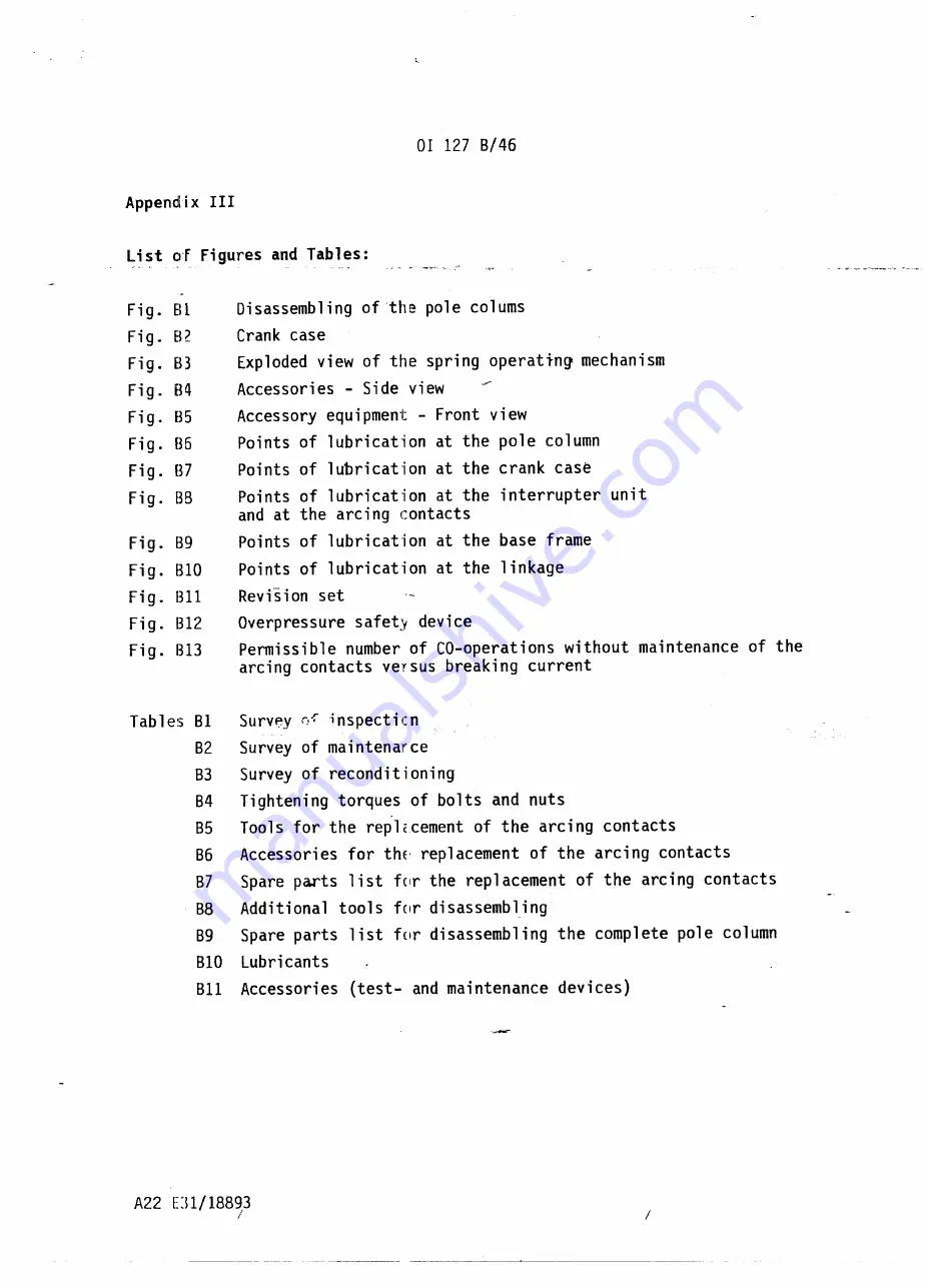
Fig.
Ell
Fig. BZ
Fig. B3
Fig.
BIl
Fi g. B5
Fig. B6
Fi g. B7
Fig. BB
Fig. B9
Fig. B10
Fig. 1311
Fig. 1312
Fig. 1313
Tables B1
B2
B3
B4
B5
B6
87
88
89
810
811
A22 D1/18893
/
Disassembling of the pole colums
Crank case
Exploded view of the spring operating mechanism
Accessories - Side view
Accessory equipment - Front view
Points of lubrication at the pole column
Points of lubricat"ion at the crank case
Points of lubrication at the interrupter
unit
and at the arcing contacts
Points of lubrication at the base frame
Points of lubrication at the linkage
ReviSion set
Overpressure safety device
Permissible number of CO-operations
without maintenance
of the
arcing contacts versus breaking current
Surv~y
r,-fi
nspect i
c
n
Survey of maintenarce
Survey of reconditioning
Tightening torques of bolts and nuts
Tools for the repl~cement of the arcing contacts
Accessori es for th'E'replacement of the arci ng contacts
Spare parts 1ist fClr the replacement
of the arci ng contacts
Additional tools for disassembl.ing
Spare parts list for disassembling
the complete pole column
Lubricants
Accessories
(test- and maintenance
devices)
Summary of Contents for SF6
Page 21: ...Fig 83 Exploded view of tle spring operating mechanism ...
Page 31: ...SF 1377 0 SF 1377 d SF 1377 0 SF 1377 0 SF 1377 _ 0 SF 1377 d SF 1377 0 SF 1377 0 ...
Page 32: ...SF 1377 c rUlUb m m I SF 1377 c J i SF 1377 SF 137 b 0 SF 1377 SF 1377 0 b ...
Page 33: ...BeruLub FK 33 Fig B8 Points of lubrication at the interrupter unit and at thE arcing contacts ...
Page 34: ...SF 1377 bl SF 1377 bl SF 1377 II 1 _ _ _ __ L i SF 1377 bl SF 1377 cl SF 1377 bl SF 1377 bl ...
Page 35: ...1 CLtl _ l1oLykote BR2 pLus l 0 ...
Page 38: ...2 7 17 2 7 18 2 7 16 2 7 02 2 7 18 2 7 03 2 7 01 2 7 06 2 7 11 2 7 07 2 7 22 ...


