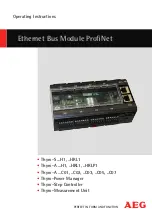
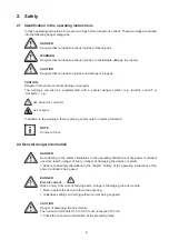
background image

Ethernet Bus Module Profi Net

PERFECT IN FORM AND FUNCTION

Operating Instructions

 Thyro-S ...H1, ..HRL1

 Thyro-A ...H1, ..HRL1, ..HRLP1

 Thyro-A …C01, ..C02, ..C03, ..C05, ..C07

 Thyro-Power Manager

 Thyro-Step Controller

 Thyro-Measurement Unit

Summary of Contents for Thyro-A C01 Series

Page 1: ...net Bus Module ProfiNet PERFECT IN FORM AND FUNCTION Operating Instructions Thyro S H1 HRL1 Thyro A H1 HRL1 HRLP1 Thyro A C01 C02 C03 C05 C07 Thyro Power Manager Thyro Step Controller Thyro Measurement Unit ...

Page 2: ...nnecting a 24 V power supply 11 4 3 Connecting the power controller to X1 X8 11 4 4 Connecting the Ethernet bus module to the master 11 5 Settings 12 5 1 Setting the protocol 12 5 2 Setting the number of slots 12 5 3 Setting the device name 12 5 4 Operating display of the bus module 13 6 Operation 14 6 1 Start configuration parameterization 14 6 2 Cyclical data transmission configuration 14 6 3 In...

Page 3: ... 1A HRL1 16 Tab 8 Cyclic input and output data for Thyro A 1A HRLP1 17 Tab 9 Cyclic input and output data for Thyro A 2A H1 17 Tab 10 Cyclic input and output data for Thyro A 2A HRL1 17 Tab 11 Cyclic input and output data for Thyro A 2A HRLP1 18 Tab 12 Cyclic input and output data for Thyro A 3A H1 18 Tab 13 Cyclic input and output data for Thyro A 3A HRL1 19 Tab 14 Cyclic input and output data fo...

Page 4: ... the following hotline AEG Power Solutions GmbH Emil Siepmann Strase 32 D 59581 Warstein Tel 49 0 2902 763 100 http www aegps de Copyright No part of these operating instructions may be transmitted reproduced and or copied by any electronic or mechanical means without the express prior written permission of AEG Power Solutions Copyright AEG Power Solutions GmbH 2010 All rights reserved Further inf...

Page 5: ...ch to 0 the Ethernet bus module becomes a ProfiNet IO device function control via LED 8 free application outputs X1 to X8 in each case terminal 5 C rail assembly 1 3 Type designation Ethernet bus module ProfiNet order no 2000 000 846 1 4 Abbreviations AEG PS AEG Power Solutions GmbH TPM Thyro Power Manager TSC Thyro Step Controller TMU Thyro Measurement Unit TIO Thyro Input Output Unit 1 5 Warrant...

Page 6: ...risk of burns In addition to the warnings there is also a general note for useful information NOTE Content of note 2 2 General danger information DANGER Not adhering to the safety stipulations in the operating instructions of the power controllers used can lead to danger of injury danger of damaging the device or system Adhere to all safety stipulations in the chapter Safety of the operating instr...

Page 7: ...nical personnel who are familiar with the pertinent safety and installation regu lations may perform the following transport installation connection commissioning maintenance testing operation These operating instructions must be read carefully by all persons working with or on the equipment prior to installation and initial start up 2 5 Intended use The device may only be used for the purpose for...

Page 8: ...ection diagrams 2 6 3 Maintenance service faults In order to avoid personal and material damages the user must observe the following Before all work Disconnect the device from all external voltage sources Secure the device against accidentally being switched back on Use suitable measuring instruments and check that there is no voltage present Ground and short circuit the device Provide protection ...

Page 9: ...X 8 5 of the bus module The power controllers can be switched over individually targeted via the bus between master setpoint and terminal X22 1 3 2 Processing the setpoint Thyro A Only local setpoints no bus setpoint Analog input at control terminal X2 4 of Thyro A Do not connect anything to terminal X22 1 of the power controller The bus module is fully functional The analog signal from the contro...

Page 10: ...ster setpoint is used If there is no IO connection then the analog setpoint is used Switching over to bus local setpoint value switchable for each controller in operation Individual setpoint from the bus module for each power controller Connect terminal X2 1 of the power controller to one of the terminals X1 5 to X8 5 of the bus module The power controllers can be switched over individually target...

Page 11: ... the power controller to X1 X8 Switch off the main power supply including the external 24 V power source and make sure these cannot be accidentally switched back on again Connect the interfaces X1 to X8 of the bus module to the system interfaces of the power controller shielded four wire cable Attention To control all parameters by ProfiNet we recommend closing the Thyro A switches S1 3 S1 4 S1 5 ...

Page 12: ...en switched on the switch Slots must first be turned to 0 Communication with the master is then interrupted Following this the desired number can be set After leaving the position 0 you have about 2 seconds time for this 5 3 Setting the device name Every IO device is identified by its device name The setting of the device name can be undertaken using for example the program Step 7 HW Config in the...

Page 13: ...oot process Red On Waiting for boot process check position of Protocol switch Off No supply voltage COM0 BF Red On No physical connection Red Flashing with 2Hz No data exchange Off The device is exchanging data with the ProfiNet IO Controller COM1 SF Red On Watchdog time out or system error Off No error Fault Red On Hardware error LED Color Status Meaning Link Green On There is an Ethernet connect...

Page 14: ...Remove device when it is switched off Not all devices are equipped with a 24 V supply connection When switching off the Thyro mains supply and the control voltage supply 24V the Thyro no longer communicates with the bus modules A switched off device will normally be displayed as pull This display can be suppressed here Deactivate Devices which are no longer accessible no communication will continu...

Page 15: ...fset Input data actual values Data type Size Unit 0 Load voltage L1 float 4 V 4 Load current L1 float 4 A 8 Mains voltage L1 integer 2 V 10 Total setpoint integer 2 4096 100 12 Fault see table 5b integer 2 14 Status see table 5b integer 2 Offset Output data setpoint Data type Size Unit 0 Master setpoint integer 2 4096 100 Description Bit LEDs Relay Frequency measurement outside of 47 Hz to 63 Hz B...

Page 16: ...ffset Input data actual values Data type Size Unit 0 Load voltage L1 float 4 V 4 Mains voltage L1 integer 2 V 6 Switch on time TS integer 2 period 8 Switch on angle alpha integer 2 0 01 el 10 Total setpoint integer 2 4096 100 12 Fault see table 14b integer 2 14 Status see table 14b integer 2 Offset Output data setpoint Data type Size Unit 0 Master setpoint integer 2 4096 100 Offset Input data actu...

Page 17: ...pe Size Unit 0 Load voltage L1 float 4 V 4 Load voltage L3 float 4 V 8 Mains voltage L1 integer 2 V 10 Mains voltage L3 integer 2 V 12 Switch on time TS integer 2 period 14 Total setpoint integer 2 4096 100 16 Fault see table 14b integer 2 18 Status see table 14b integer 2 Offset Output data setpoint Data type Size Unit 0 Master setpoint integer 2 4096 100 Offset Input data actual values Data type...

Page 18: ...otal setpoint integer 2 4096 100 40 Fault see table 14b integer 2 42 Status see table 14b integer 2 Offset Output data setpoint Data type Size Unit 0 Master setpoint integer 2 4096 100 Offset Input data actual values Data type Size Unit 0 Load voltage L1 float 4 V 4 Load voltage L2 float 4 V 8 Load voltage L3 float 4 V 12 Mains voltage L1 integer 2 V 14 Mains voltage L2 integer 2 V 16 Mains voltag...

Page 19: ...tatus see table 14b integer 2 Offset Output data setpoint Data type Size Unit 0 Master setpoint integer 2 4096 100 Offset Input data actual values Data type Size Unit 0 Load voltage L1 float 4 V 4 Load voltage L2 float 4 V 8 Load voltage L3 float 4 V 12 Load current L1 float 4 A 16 Load current L2 float 4 A 20 Load current L3 float 4 A 24 Power L1 float 4 W 28 Power L2 float 4 W 32 Power L3 float ...

Page 20: ...12 none closed Low power limit Bit 13 none closed High power limit Bit 14 none closed Description Bit LEDs Relay Pulse inhib active bridge X2 1 X2 2 open Bit 0 Pulse Inhibit LED on closed Mains frequency is 60Hz Bit 2 none closed U limiting Bit 4 Pulse Inhibit LED and Load Fault LED flashing alternately slowly closed I limiting Bit 5 Pulse Inhibit LED and Load Fault LED flashing alternately slowly...

Page 21: ...phase 1 float 4 A 8 Load current phase 2 float 4 A 12 Total load current float 4 A 16 Mains voltage L1 integer 2 V 18 Switch on angle alpha phase 1 integer 2 0 01 el 20 Total setpoint integer 2 4096 100 22 Fault see table 14b integer 2 24 Status see table 14b integer 2 Offset Output data setpoint Data type Size Unit 0 Master setpoint integer 2 4096 100 Tab 17 Cyclic input and output data with Thyr...

Page 22: ...h Thyro A 1A C07 Offset Input data actual values Data type Size Unit 0 Load voltage L1 float 4 V 4 Load current L1 float 4 A 8 Power L1 float 4 W 12 Mains voltage L1 integer 2 V 14 Load temperature integer 2 C 16 Switch on angle alpha integer 2 0 01 el 18 Total setpoint integer 2 4096 100 20 Fault see table 14b integer 2 22 Status see table 14b integer 2 Offset Output data setpoint Data type Size ...

Page 23: ...ut 3 integer 2 4096 100 26 Mains voltage integer 2 V 28 Period duration integer 2 μs 30 Temperature integer 2 C 32 Fault see table 25b integer 2 34 Status see table 25b integer 2 Offset Input data actual values Data type Size Unit 0 AC input 1 float 4 A V 4 AC input 2 float 4 A V 8 AC input 3 float 4 A V 12 Power float 4 W 16 Energy float 4 kWh 20 DC input 1 integer 2 4096 100 22 DC input 2 intege...

Page 24: ...teps integer 2 40 Total setpoint Integer 2 4096 100 Offset Output data setpoint Data type Size Unit 0 Master setpoint integer 2 4096 100 Offset Input data actual values Data type Size Unit 0 AC input 1 float 4 A V 4 AC input 2 float 4 A V 8 AC input 3 float 4 A V 12 Power float 4 W 16 Energy float 4 kWh 20 DC input 1 integer 2 4096 100 22 DC input 2 integer 2 4096 100 24 DC input 3 integer 2 4096 ...

Page 25: ...fault output Frequency measurement outside of 47Hz to 63Hz Bit 0 on SYNC error no cero crossing within the gate Bit 1 on Temperature max limit has been exceeded Bit 2 on Temperature min limit has been exceeded Bit 3 on One or more parameters outside the limits Bit 4 on Mains voltage lower than lower voltage limit Bit 5 on Description Bit Alarm LED alarm output Mains frequency is 60Hz Bit 2 off Tra...

Page 26: ...ecord and the new value must be entered At step 7 and when using the SFB 53 the Logical Address of the slot is to be entered instead of the slot Error code Meaning DE80B000 The unit does not recognize the parameter invalid index DE80B100 The length entry of the parameter is incorrect DE80B200 The projected slot is not occupied DE80B300 The actual unit type does not match the set unit type Error co...

Page 27: ...to X11 current consumption approx 150mA The foregoing circuit diagram shows the connection of the bus module supply 24V DC approx 150mA bridge contact Thyro S see chapter 3 1 Thyro a see chapter 3 2 TPM see chapter 3 3 X1 X8 to the power controllers ...

Page 28: ...pin connector of slots X1 to X8 1 Switched ground potential All pins 1 of slots X1 X8 are connected 2 RxD 3 TxD 4 Ground 5 Switchable ground potential The slots X1 X8 can be switched as desired 6 Ground 7 Ground potential for shield connection Configuration of the 3 pin connector X11 X11 24V X11 24V ground X11 Grounding carry out by as short a route as possible ...

Page 29: ...d with 8bit no parity one stop bit The protocol begins with STX followed by an identifier the data and is concluded with a check sum Defective protocols are ignored 8 2 Ethernet interfaces Communication medium CAT 5e Network topology tree star and line Maximum cable length 100m ProfiNET participants restricted to the maximum supported number of devices by the con troller used PNO identification nu...

Page 30: ...s setpoint analog input bus setpoint analog input bus setpoint analog input group switching selective switching bus setpoint analog input bus setpoint analog input bus setpoint analog input bus setpoint analog input analog input is active setpoint setpoint 1 setpoint 1 setpoint 2 setpoint 2 setpoint 8 setpoint 8 blank ...

Page 31: ...ctive switching bus setpoint is active analog input is active setpoint blank bus setpoint analog input bus setpoint analog input bus setpoint analog input bus setpoint analog input bus setpoint analog input bus setpoint analog input setpoint 1 ON OFF setpoint 1 ON OFF setpoint 2 ON OFF setpoint 2 ON OFF setpoint 8 ON OFF setpoint 8 ON OFF ...

Page 32: ...up switching selective switching bus setpoint is active analog input is active bus setpoint analog input bus setpoint analog input bus setpoint analog input bus setpoint analog input bus setpoint analog input bus setpoint analog input setpoint 1 setpoint 2 setpoint 8 setpoint 1 setpoint 2 setpoint 8 setpoint blank ...

Page 33: ...dard ISO 9001 Should there be faults in spite of this our 24 hour service hotline is on hand tel 49 0 2902 763 100 13 Technical Data Power supply 24V DC 150mA Connection options for up to 8 AEG power controllers of series Thyro S Thyro A and the TPM series Function control LED Assembly DIN rail Ambient temperature maximum 55 C Dimensions WxDxH 150 x 60 x 95 mm Weight circa 0 35 kg ...

Page 34: ... 000 849 Bus module connection cable for 4 controllers 1 5 m long 16 Approvals and conformity Quality standard in acc with EN ISO 9001 CE conformity ProfiNet conformity RoHS compliant 5 6 Directives The CE mark on the device confirms compliance with the EC directives 2006 95 EEC for low voltage and 2004 108 EEC for electromagnetic compatibility if the instructions on installation and commissio nin...

Page 35: ... B 10 C 55 C Humidity class B EN 50 178 tab 7 EN 60 721 Degree of contamination 2 EN 50 178 tab 2 Air pressure 900mbar 1000m above sea level Degree of protection IP00 EN 69 529 EMC testing EN 61000 6 2 4 Emitted interference CISPR 16 Radiated immunity EN IEC 61000 4 3 Conducted immunity EN IEC 61000 4 6 ESD 8kV A EN IEC 61000 4 2 Burst control lines 1kV A EN 61000 4 4 ...

Page 36: ...al value output 1 u16 0 4096 30 SPG_MIN Mains voltage monitoring min u16 0 1000 31 SPG_MAX Mains voltage monitoring max u16 0 1000 32 UN_S Undercurrent monitoring u16 0 1 on off 33 RELAIS_CTRL_2 Relay configuration 2 u16 0 65535 bit coded 34 LASTBRUCH_MIN_ABS Load fault minimum value u16 0 4505 36 SYNC_ADR Synchro cycle address u16 0 65535 37 IMAB Pulse switch off in case of failure u16 0 65535 bi...

Page 37: ... 24 4096 100 r x x x x x x x x x x x x x x x 27 20 4096mA r w x x x x x x x x x x 0mA S1 9 28 1 819 r w x x x x x x x x x x 1 R 204 29 V r w x x x x x x x x x x x x x x x type 30 V r w x x x x x x x x x x x x x x x type 31 r w x x x x x x x x x x x off R 205 32 r w x x x x x x x x x x 0 33 100 4096 r w x x x x x x x x x x x 0 R 205 34 period 2 r w x x x x x x x x x x x 100 36 r w x x x x x x x x x...

Page 38: ...u16 0 4096 30 SPG_MIN Mains voltage monitoring min u16 0 1000 31 SPG_MAX Mains voltage monitoring max u16 0 1000 32 UN_S Undercurrent monitoring u16 0 1 off on 33 RELAIS_CTRL_2 Relay configuration 2 u16 0 65535 bit coded 34 LASTBRUCH_MIN_ ABS Load fault minimum value u16 0 4505 36 SYNC_ADR Synchro cycle address u16 0 65535 37 IMAB Pulse switch off in case of failure u16 0 65535 bit coded 38 STA_RE...

Page 39: ...0V R202 21 0 1A r w 110A R203 22 W r w 0 R202 23 r 0 24 4096 100 r 27 20 4096mA r w 0mA S1 9 28 1 819 r w 1 R204 29 V r w type 30 V r w type 31 r w off R205 32 r w 0 33 100 4096 r w 0 R205 34 period 2 r w 100 36 r w 0 37 20 4096mA r w 0mA S1 6 38 20 4096mA r w 20mA 39 r w type 41 r w 6 42 r 44 r 45 r 46 r w off 48 r w 447 49 r w off 50 r w 100 56 C r 84 r w 100 109 20 4096mA r w 0mA S1 9 110 1 819...

Page 40: ...F Offset 4 u16 0 4095 49 DAC4_FA Scale end value 4 u16 0 4096 50 DAC4_CTRL Output value 4 u16 1 16 transformer1 transformer2 transformer3 U mains setpoint1 setpoint2 R309 R310 temp res controller1 controller6 51 DAC5_OF Offset 5 u16 0 4095 52 DAC5_FA Scale end value 5 u16 0 4096 53 DAC5_CTRL Output value 5 u16 1 16 transformer1 transformer2 transformer3 U mains setpoint1 setpoint2 R309 R310 temp r...

Page 41: ...w 0 42 1 819 r w 819 43 r w 2 44 4096 10V r w 0 45 1 819 r w 819 46 r w 3 47 4096 10V r w 0 48 1 819 r w 819 49 r w 4 50 4096 10V r w 0 51 1 819 r w 819 52 r w 9 53 4096 10V r w 0 54 1 819 r w 819 55 r w 16 56 r w 100 57 r w 3473 58 r w 4541 59 r w 5118 R310 60 r w 5118 R310 61 r w 5118 R310 62 r w 16399 63 r w 127 64 r w 504 66 r 68 r 69 r 70 r w 0 72 h r 74 C r w 80 76 kWh r 99 r 105 r 106 r 107...

Page 42: ...former3 U mains setpoint1 setpoint2 R309 R310 temp res controller1 controller6 48 DAC4_OF Offset 4 u16 0 4095 49 DAC4_FA Scale end value 4 u16 0 4096 50 DAC4_CTRL Output value 4 u16 1 16 transformer1 transformer2 transformer3 U mains setpoint1 setpoint2 R309 R310 temp res controller1 controller6 51 DAC5_OF Offset 5 u16 0 4095 52 DAC5_FA Scale end value 5 u16 0 4096 53 DAC5_CTRL Output value 5 u16 ...

Page 43: ... 10V r w 0 39 1 819 r w 819 40 r w 1 41 4096 10V r w 0 42 1 819 r w 819 43 r w 2 44 4096 10V r w 0 45 1 819 r w 819 46 r w 3 47 4096 10V r w 0 48 1 819 r w 819 49 r 4 50 4096 10V r w 0 51 1 819 r w 819 52 r w 9 53 4096 10V r w 0 54 1 819 r w 819 55 r w 16 56 r w 100 57 r w 3473 58 r w 4541 59 r w 5118 R310 60 r w 5118 R310 61 r w 5118 R310 62 r w 16399 63 r w 127 64 r w 504 66 r 68 r 69 r 70 r w 0...

Page 44: ...emp res controller1 controller6 51 DAC5_OF Offset 5 u16 0 4095 52 DAC5_FA Scale end value 5 u16 0 4096 53 DAC5_CTRL Output value 5 u16 1 16 transformer1 transformer2 transformer3 U mains setpoint1 setpoint2 R309 R310 temp res controller1 controller6 54 DAC6_OF Offset 6 u16 0 4095 55 DAC6_FA Scale end value 6 u16 0 4096 56 DAC6_CTRL Output value 6 u16 1 16 transformer1 transformer2 transformer3 U m...

Page 45: ...19 46 r w 3 47 4096 10V r w 0 48 1 819 r w 819 49 r w 4 50 4096 10V r w 0 51 1 819 r w 819 52 r w 9 53 4096 10V r w 0 54 1 819 r w 819 55 r w 16 56 r w 100 57 r w 3473 58 r w 4541 59 r w 5118 R310 60 r w 5118 R310 61 r w 5118 R310 62 r w 16399 63 r w 127 64 r w 504 66 r 68 r 69 r 70 r w 0 72 h r 74 C r w 80 76 kWh r 99 r 105 r 106 r 107 r 108 r 109 r 110 4096 100 r 119 r 121 r 123 r 124 r w 1709 1...

Page 46: ...mp res controller1 controller6 51 DAC5_OF Offset 5 u16 0 4095 52 DAC5_FA Scale end value 5 u16 0 4096 53 DAC5_CTRL Output value 5 u16 1 16 transformer1 transformer2 transformer3 U mains setpoint1 setpoint2 R309 R310 temp res controller1 controller6 54 DAC6_OF Offset 6 u16 0 4095 55 DAC6_FA Scale end value 6 u16 0 4096 56 DAC6_CTRL Output value 6 u16 1 16 transformer1 transformer2 transformer3 U ma...

Page 47: ...19 46 r w 3 47 4096 10V r w 0 48 1 819 r w 819 49 r w 4 50 4096 10V r w 0 51 1 819 r w 819 52 r w 9 53 4096 10V r w 0 54 1 819 r w 819 55 r w 16 56 r w 100 57 r w 3473 58 r w 4541 59 r w 5118 R310 60 r w 5118 R310 61 r w 5118 R310 62 r w 16399 63 r w 127 64 r w 504 66 r 68 r 69 r 70 r w 0 72 h r 74 C r w 80 76 kWh r 99 r 105 r 106 r 107 r 108 r 109 r 110 4096 100 r 119 r 121 r 123 r 124 r w 1709 1...

Page 48: ...2902 763 520 290 Fax 49 0 2902 763 1201 www aegpowercontrollers com www aegps com AEG is a registered trademark used under license from AB Electrolux Betriebsanleitung Operating Instructions 8000029997 BAL en 07 10 printed in Germany subject to change without notice ...

Reviews: