background image


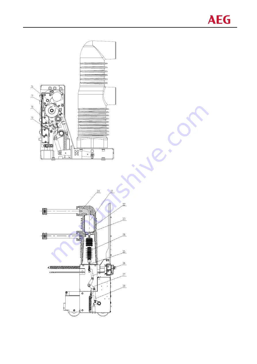
16 

energy storage keeping block 

17 energy storage latch 

18 

closing interlock block


19 

handcart interlock block


Fig. 2 side view of operating mechanism           


20 

upper terminal


21 

vacuum chamber


22 fixed pole 

23 

lower terminal


24 insulating pull rod 

25 threaded rod 

26 connecting plate 

27 crank arm 

28 connecting plate 


Fig. 3 internal structure diagram of circuit breaker (floor type) 

Summary of Contents for VB 40.5

Page 1: ...VB 40 5 Vacuum Circuit Breaker VB 40 5真空断路器 User Manual 册 ...

Page 2: ......

Page 3: ...meters Attention must be paid to any identification of circuit breakers It is necessary to ensure the applicability and safety of interlocking conditions and working procedures of circuit breakers It is not allowed to carry out maintenance work when the switch cabinet and secondary control circuit are charged It must be ensured that the circuit breaker is not impacted by any external force otherwi...

Page 4: ...le 1 3 Technical parameter 5 4 Propulsion mechanism 7 5 Overall dimensions 8 6 Electrical wiring diagram 12 7 Installation commissioning and operation 14 8 Maintenance 15 9 Transportation and storage 17 10 Random documents 17 11 Spare parts 17 ...

Page 5: ...age relative humidity 90 Daily average saturated vapor pressure 2 2 10 3 Mpa Monthly average saturated vapor pressure 1 8 10 3 Mpa Earthquake intensity No higher than Level 8 Altitude 1000m conventional products can be used below 1000m above sea level and high altitude products need to be noted when ordering Others no inflammable and explosion hazard no chemical corrosive gas and no violent vibrat...

Page 6: ...ils auxiliary switch indicating device and other components in the mechanism box the front is provided with closing and opening button manual energy storage operation hole spring energy storage status indicator board and closing and opening indicator board Fig 1 2 1 closing spring 2 closing opening indicator 3 opening latch 4 charging indicator 5 counter 6 micro switch 7 charging motor 8 manual ch...

Page 7: ...9 handcart interlock block Fig 2 side view of operating mechanism 20 upper terminal 21 vacuum chamber 22 fixed pole 23 lower terminal 24 insulating pull rod 25 threaded rod 26 connecting plate 27 crank arm 28 connecting plate Fig 3 internal structure diagram of circuit breaker floor type ...

Page 8: ...o close After the closing action is completed the opening holding switch and the opening half shaft are kept in the buckle state At the same time the energy storage indicator board and auxiliary switch are reset and the motor power supply circuit is connected If the external power supply is also connected it will enter the energy storage state again and the connecting rod will pull the on off indi...

Page 9: ...lling out or pushing the load area in the closing state 5 If electrical closing locking is selected manual closing operation is prevented when the secondary control power supply is not connected 3 Technical parameter 3 1 Main technical parameter No Item Unit Value 1 Rated voltage kV 40 5 2 Rated power frequency withstand voltage 1 min 95 118 Rated lightning impulse withstand voltage 185 215 3 Rate...

Page 10: ...ge closing speed m s 0 5 1 0 9 Opening time rated voltage ms 20 50 10 Closing time rated voltage ms 30 70 11 Opening closing rating voltage V AC 110 220 DC 110 220 12 Rated voltage of energy storage motor V AC 110 220 DC 110 220 13 Main loop resistance μΩ 630 1250A 55 1600 2000A 45 above 2500A 35 14 Energy storage time s 10 3 3 Technical parameters of operating mechanism and locking electromagnet ...

Page 11: ...e click sound of clutch slipping can be heard and the handcart does not move At this time the shaking of the operating handle should be stopped The advancement and withdrawal of the circuit breaker handcart in the cabinet shall be flexible without obvious jamming Note when the circuit breaker touches the valve mechanism of the cabinet and is almost in place the propulsion force should be significa...

Page 12: ...8 5 Overall dimensions Floor type 300mm apart ...

Page 13: ...9 Floor type 440mm apart ...

Page 14: ...10 Withdrawable 275mm apart Fixed connection 300mm apart ...

Page 15: ...11 Fixed connection 300mm apart ...

Page 16: ...12 6 Electrical wiring diagram Floor type 58 core with auxiliary contact of propulsion mechanism ...

Page 17: ...13 Withdrawable 58 cores ...

Page 18: ... with lifting mark on the circuit breaker When moving the upper and lower outlet arms shall not be stressed and the circuit breaker shall not be subject to large impact and vibration 7 2 In case of problems in operation determine the causes according to the table below If it can t be solved please contact the manufacturer Do not disassemble the circuit breaker by yourself ...

Page 19: ... such a phenomenon it should be eliminated before power on to restore to normal working conditions Remove dirt especially on the surface of insulating parts These may be due to contamination during transportation or storage which may affect the insulation performance of the product Check the connection status of primary circuit contact secondary circuit connection and grounding body Manual operati...

Page 20: ... times Cut off the energy storage power supply and operate the circuit breaker to close and open once to release energy Re apply grease to supporting shaft rolling and sliding bearing Check the correctness of each component function during electrical and mechanical action Check the condition or looseness of fasteners installed at connecting rod crank arm and supporting rod During maintenance it is...

Page 21: ...t should be hooked at the lifting position with lifting mark 9 4 The circuit breaker shall be stored in the state of opening of operating mechanism and energy storage spring without energy storage Basic storage requirements The dry and well ventilated storage room shall meet the relevant provisions of GB T 1984 and IEC 60694 The temperature of the storage room shall not be lower than 15 C Do not d...

Page 22: ...ng auxiliary switch QF 26490090 Handcart position auxiliary switch S8 S9 26490580 Energy storage position switch S1 S2 S3 26490598 Position locking switch 110V 26490076 Position locking switch 220V 26400055 Closing Opening coil 110V 26400054 Closing Opening coil 220V 26490375 12kV breaker energy saving motor 100W 110V 26490359 12kV breaker energy saving motor 100W 220V 26490349 Pushing handle for ...

Page 23: ... 必须遵守本 册的要求 断路器的使 场合应符合 内正常的环境使 条件 对断路器的任何操作和维护都应该由经过专业培训的专职电 员进 禁 把断路器置于超出其额定参数的情况下运 必须注意断路器的任何标识 必须保证断路器的联锁条件和 作规程的适 性和安全性 不能在开关柜及 次控制回路带电的情况下从事检修 作 必须确保断路器不受任何外力的冲击 否则将损坏设备 对断路器的任何违规操作均可能损坏设备 甚 引起严重事故 应把本 册放在可以 便拿到的地 应由专业 员负责断路器的安全管理 ...

Page 24: ...20 目录 概述 21 结构原理 21 技术参数 24 推进机构 26 外形尺寸 27 电 接线图 31 安装 调试与操作 33 维护与保养 34 运输与储存 35 随机文件 36 备品备件 36 ...

Page 25: ...均相对湿度 90 日平均饱和蒸汽压 2 2X10 3 MPa 月平均饱和蒸汽压 1 8X10 3 MPa 地震强度 8度 海拔 度 1000m 常规产品满足海拔1000m以下使 海拔产品需在订货时注明 其他 使 场所 易燃和爆炸危险 化学腐蚀性 体以及 剧烈震动 注 当使 环境不同或有其它特殊要求时需与制造厂协商 2 结构原理 2 1 主体结构 断路器采 体化和模块化设计 整体结构简单合理 采 上下置 灭弧室部分在上面 联锁和操动机 构部分在下面 使 专 的弹簧操动机构 需调整 动作稳定可靠 断路器三相导电回路的真空灭弧室布置在封闭的固封极柱内 这样不仅使相间绝缘性能显著提 而且 使每相回路不受外界恶劣环境的影响 可以防 灰尘和异物进 导电回路 并缩 了断路器的整体尺寸 2 2 操动机构 操动机构为弹簧储能机构 机构箱内有合闸单元 由 个或几个脱扣线圈组成的分闸单元 辅助开 关 指示装置等...

Page 26: ...22 1 合闸弹簧 2 合分闸指示 3 分闸半轴 4 储能指示 5 计数器 6 微动开关 7 储能电机 8 动储能轴 9 电机输出轴 10 齿轮 11 齿轮 12 合闸线圈 13 合闸板 14 分闸线圈 15 过流线圈或第 分闸线圈 图 1 断路器操动机构正视 16 储能保持挚子 17 储能保持块 18 合闸联锁板 19 车联锁板 图2 断路器操动机构侧视 ...

Page 27: ...动进 电动储能时由电机输出轴 带动齿轮系统进 动储能时通过 动储能轴 带动齿轮系统进 齿轮转 动时 带动 齿轮 起运动 从而拉动储能弹簧进 储能 到达储能位置时 储能保持挚子顶住储能保持 块 使离合器分离 保持储能状态 储能指示牌显示拉簧拉伸状态 储能完成 微动开关切断储能电机供 电电源 此时断路器处于合闸准备状态 合闸 在合闸过程中 不论 动按下 合闸 按钮或远 操作使合闸线圈 动作 均可使储能保持挚子转 离储能保持块 在合闸弹簧力的作 下 带动凸轮转动 凸轮又驱动连杆机构带动绝缘拉杆 和灭弧室 的动触头进 合闸 合闸动作完成后分闸保持挚子与分闸半轴保持扣接状态 同时储能指示牌 辅助开关复位 电机供电 回路接通 若外接电源也接通则再次进 储能状态 连杆拉动合分指示牌 指示 的位置 同时拉动 计数器实现计数 传动连杆拉动主轴 带动辅助开关切换 ...

Page 28: ...辅助开关切换 防误联锁 断路器能提供完善的防误联锁操作功能 断路器合闸操作完成后 合闸联锁板 转动顶住合闸板 在断路器未分闸时将不能再次合闸 断路器在合闸结束后 如合闸电信号未及时去除 断路器内部防跳控制器将切断合闸回路防 多次 重合闸 断路器在没有到达试验位置或 作位置时 由 车联锁板 扣住合闸板 同时切断合闸回路 防 断路器处于合闸状态进 负荷区 断路器在 作位置或试验位置合闸后 由滚轮压住推进机构 车将 法移动 防 在合闸状态拉 出或推进负荷区 如果选 电 合闸闭锁 在 次控制电源未接通情况下阻 动进 合闸操作 3 技术参数 主要技术参数 序号 名 称 单 位 数 值 额定电压 kV min 频耐受电压 有效值 相间 相对地 断口 雷电冲击耐受电压 峰值 相间 相对地 断口 额定频率 Hz 额定电流 A 额定短路持续时间 s 额定短路开断电流 kA 额定短时耐受电流 额定短路关合电流...

Page 29: ... s CO 分合闸电磁铁额定电压 V AC DC 储能电机额定电压 V AC DC 分级 级 E M C 机械特性参数 序号 参数名称 单位 参数值 额定电流 A 触头开距 mm 固封 筒式 接触 程 超 程 mm 三相合闸不同期 ms 三相分闸不同期 ms 触头合闸弹跳时间 ms 平均分闸速度 m s 平均合闸速度 m s 分闸时间 ms 合闸时间 ms 额定合 分闸操作电压 V AC DC 储能额定电压 V AC DC 各相导电回路电阻 μΩ A A A 以上 储能时间 s ...

Page 30: ...处于插 位置 如推进机构不带接地联锁 此步骤可以跳过 车的推进和退出 使断路器处于分闸状态 动或电动 把联锁片 的活门打开 插 操作 柄 可使断路器 车在柜 体内推进和退出 当 车进到 作位置或退到试验位置时 可听到离合器打滑的 咔嚓 声 车不再移 动 此时应停 摇动操作 柄 断路器 车在柜体内的推进和退出应灵活并 明显的卡滞现象 注意 在 断路器碰上柜体的活门机构和快到位时 推进力要明显加 这属正常现象 合闸操作 将 车推进柜内 操作左右把 位置 A 分接地开关 操作接地联锁 把 位置 A 按下联锁片 摇把顺时针转动主操作轴 使断路器推进 柜内 作位置 合上联锁片 合断路器 运 紧急分闸 开关柜在紧急情况时 紧急分闸 把 逆时针旋转 可使断路器分闸 图示说明 作位置 左 右把 联锁片 紧急分闸 把 接地联锁 把 插销 图 4 推进机构示意图 ...

Page 31: ...27 5 外形尺寸 落地式 相距300mm ...

Page 32: ...28 落地式 相距 440m ...

Page 33: ...29 车式 相距275mm 固定式 相距 300mm ...

Page 34: ...30 固定式 相距 300mm ...

Page 35: ...31 6 电气接线图 落地式 58芯 带推进机构辅助接点 ...

Page 36: ...32 车式 58芯 ...

Page 37: ...33 固定式 7 安装 调试与操作 7 1 断路器从包装箱中起吊时 挂钩应挂在断路器上有起吊标志的起吊位置处 移动时不得使上 下 出线臂受力 同时不应让断路器受到较 的冲击震动 7 2 在操作中遇到问题 先按照下表确定原因 如不能解决 请与制造厂联系 切勿 对断路器拆 装 ...

Page 38: ...常 的 作条件 清除污垢 尤其是绝缘件表面的脏污 这些可能是由于在运输或储存过程造成的脏污会影响产品绝 缘性能 检查 次回路接触 次回路连接和接地体的连接状态 动操作试验 8 维护与保养 必须由AEG公司 员或对本设备熟悉并经培训合格的 员进 维修 如由 员进 维 修 则由 承担相应维修后果责任 8 1 在正常使 期间 断路器免维护 由于断路器具有结构简单和耐 的特点 因此有很 的使 寿 命 维护 作与零部件受磨损和 化情况有关 为使断路器可靠地 作 所需进 地维护 作的间隔时间 和检修范围将取决于 作环境的影响 操作次数 运 时间以及短路电流开断的次数等诸因数 8 2 在进 维护 作前 所有的辅助电源均必须断开且没有再送电的危险 断路器本 处于分闸且弹 簧未储能状态 为防 意外事故 在对操作机构上进 的各项 作应格外 心 8 3 拆卸和更换断路器零部件 应由本公司 员或相应的受过培训的 ...

Page 39: ...运 了约5年之后或当操作机构进 维护时 也应对断路器本体进 检查 尤其是检查 外观情况的同时 也需检查设备表面的污秽 受潮及腐蚀情况 干布清洁绝缘件表面的灰尘 然后 粘 有家 碱性清洗剂或安全清洗剂的绸布揩去各种污秽物 应注意所使 的清洁剂是否适 于塑料和合成橡㬵 材 不得使 四氯化碳或三氯 烯去清揩 在 些特殊使 场合或有损害的环境条件下运 的开关设备 如在 污秽和重腐蚀性 体的环境条件 中 上述检查 作的最短间隔时间应 于5年 9 运输与储存 9 1 产品运输时 断路器应处于分闸且弹簧未储能的状态下装 封闭的包装箱内加以固定 内置适量 干燥剂 断路器应 塑料薄膜加以保护 以防在装卸时渗 和在存储时侵 灰尘 9 2 装卸包装箱应采 以下 具 起重机 叉车 车 9 3 运输途中应注意如下事项 避免冲击 避免其它破坏性的机械力 起吊器具不应搭钩在断路器本体或操作机构上 而应搭钩在断路器有起吊...

Page 40: ...格证 b 出厂检验报告 c 装箱单 11 备品备件 当 需要时 可按照下述确定所需备件 并在订货时提出 以备不时之需 订货号 SAP 产品型号 过流脱扣线圈 Y 过流线路板 合闸闭锁电磁铁 S 合分闸控制线路板 需注明 操作电压 有 防跳 有 闭锁 合分闸辅助开关 QF 车位置辅助开关 S S 储能微动开关 S S S 位置闭锁开关 V 位置闭锁开关 V 合分闸线圈 V 合分闸线圈 V 断路器储能电机 V 断路器储能电机 V 断路器摇进 柄 机构储能 柄头 计数器 推进机构 柄 ...

Page 41: ...官 网址 www aeg imc com 热线电话 400 820 5234 册如有修改 恕不另 通知 版本号 2022IM602 GEIS BREAKERS SHANGHAI CO LTD An AEG Company ...

Reviews: