background image

APPENDIX

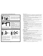
DRY CONTACT

N.C.

N.O.

TRANSISTOR OPEN COLLECTOR OUTPUT

A dry contact means that no electricity was connected to it. It is prepared for free connections. The Relay
Output contacts provided in this keypad system are dry contacts.

Normally Closed, the contact is closed circuit at normal status. It is open circuit when active.

Normally Open, the contact is open circuit at normal status. It is closed circuit when active.

An open collector output is equivalent to a Normally Open (N.O.) contact referring to ground similar to a relay
contact referring to ground. The transistor is normally OFF, and its output switches to ground (-) when active.
The open collector can only provide switching function for small power but it is usually good enough for
controlling of an alarm system. The Duress, Inter-lock, Key Active Outputs of the keypad are open collector
output.

( )

OPEN COLLECTOR
OUTPUT ----
Output switches to
ground when activates

( )

N.O. CONTACT
OUTPUT ----
Output switches to
ground when activates

EQUIVALENT

20

40IN9523

M-

100705

R

SINCE 1979

ADVANCED ELECTRONICS

INDUSTRY

MANUFACTURED BY:

An Innovative Product
Developed By:

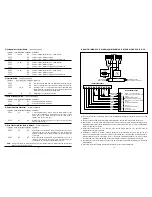
(F) OUTPUT 3

(WHITE/RED WIRE)

Output 3 is an open collector output prepared for

auxiliary controls. It may be used for arm-disarm
of a security system, enable and disable of a

keypad or a protection zone etc.; it can also
drive a relay to give full function of N.C. and N.O.

outputs as like the output 2 making the keypad a
ture 3 output system.

EXTERNAL

RELAY

+12V

N.C.

COM

N.O.

(9)
(10)
(11)
(12) WHITE/RED
(13)
(14)

WIRE HARNESS

MULTI-PURPOSE SELF-CONTAINED

DIGITAL ACCESS CONTROL KEYPAD

DK-9523

Programming & Installation Manual

FOR ELECTRIC LOCK, INTER-LOCK

AND SECURITY SYSTEM INSTALLATIONS

AEI  PROTECT - ON

SYSTEMS LIMITED

Summary of Contents for DK-9523

Page 1: ...of an alarm system The Duress Inter lock Key Active Outputs of the keypad are open collector output OPEN COLLECTOR OUTPUT Output switches to ground when activates N O CONTACT OUTPUT Output switches t...

Page 2: ...OUTPUT 2 1 Amp relay WHITE ORANGE DURESS OUTPUT YELLOW GREEN GND BROWN INTERLOCK CONTROL ORANGE OUTPUT 1 INHIBIT WHITE RED OUTPUT 3 OUTPUT 2 RELAY PURPLE N C YELLOW LIGHT BLUE GREEN GREY BLACK RED RED...

Page 3: ...if it is not used Connect to 12 24V AC or DC power supply The supply and GND wire 15 are the common grounding points of the keypad system No selection jumper is required for the full input voltage ran...

Page 4: ...lamp changes to steady Red while the auxiliary Red LED is energized The built in buzzer and the green LED indicator at the centre give the following tones and signals for operation status All Pacifier...

Page 5: ...quired to apply the following procedures precisely Disconnect power supply Displace the DAP jumper from OFF to ON position Reconnect power supply buzzer is activated Put the DAP jumper back to OFF pos...

Page 6: ...g Installer Programming NOTE Locations Code of Duration Locations No of False Entry Validation Comments Validation Comments Locations Code of Functions Validation Comments Locations Code of Functions...

Page 7: ...is always set with Auto Code Entry in default The user does not require to press the key in user code entry The user only needs to enter the 4 digit user code The relay will activate for the programm...

Page 8: ...ressed Multi User Mode on Duty please wait 2 3 seconds until the confirmation beeps are heard after the key is pressed SET THE SYSTEM TO SINGLE USER MODE SET THE SYSTEM TO MULTI USER MODE REFRESH THE...

Page 9: ...for output 2 3 and the key to delete a user code You may delete other user code s in this fashion Exit the programming mode by pressing the key after the work is done 1 2 3 4 3289 1 05 The keypad is...

Page 10: ...Code of The Accelerated Code will be Duress output activates output switches to ground Output 1 activates for 1 second Output 1 starts Output 1 stops 0321 83 8321 8321 83 C MULTI USER MODE OPERATION...

Reviews: