16
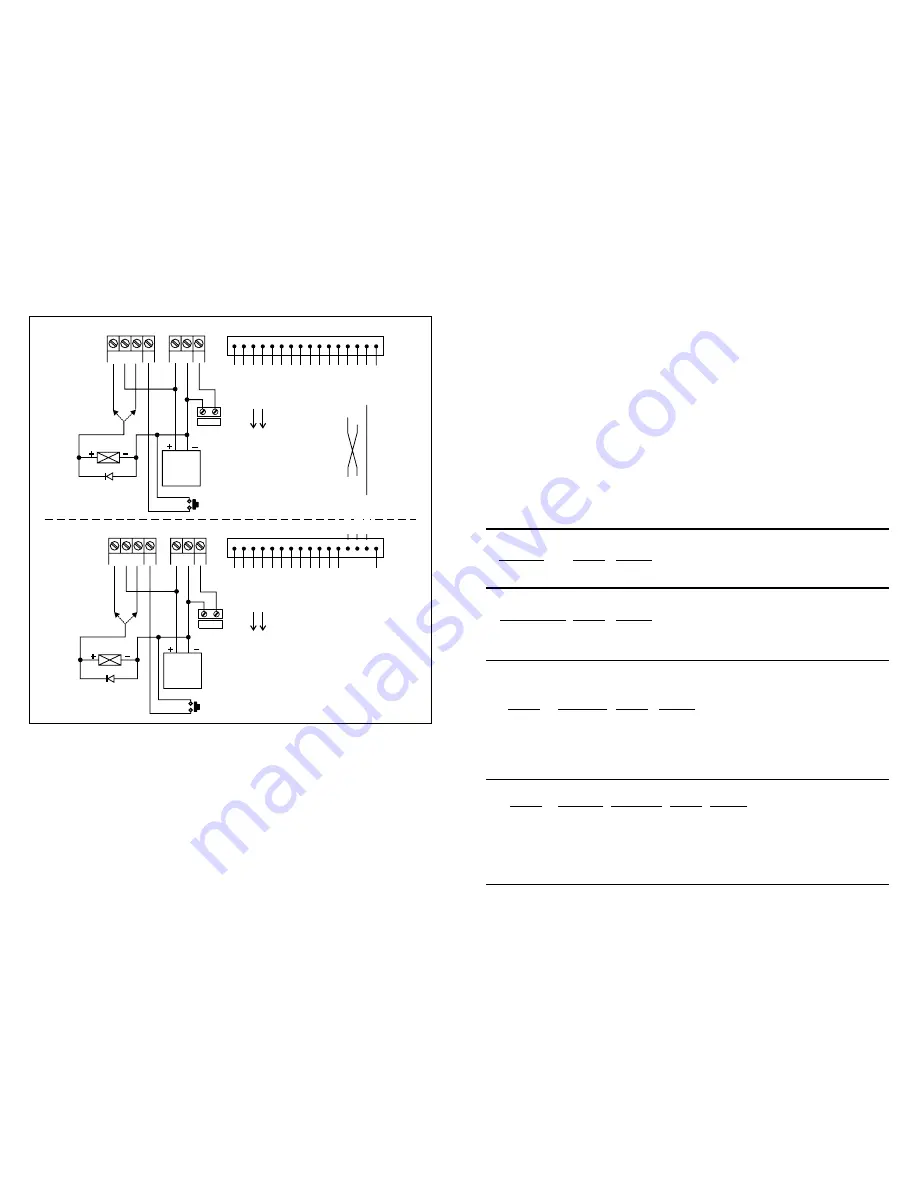
3) BASIC WIRINGS OF AN INTER-LOCK SYSTEM USING TWO KEYPADS
An inter-lock system needs two door controllers. This application example uses two DK-9523 with simple cross wire
connection on their "Output 1 Inhibit" and "Inter-lock Control Output" terminals. It is necessary to link up the "( )
GND" terminals of the two keypads as common ground to achieve the inter-lock logical functions. The connection of
the Green LED is optional. It will light up for lock active if connected.
Use keypad to open the door from outside.
Press egress button to open the door from inside.
Connect the door magnetic sensors on the door 1 and door 2 to monitor their positions.
During the time that door 1 is open, then, door 2 is forced to keep closed, or vice versa.
Use N.O. Relay output for fail-secure locking device; and N.C. output for fail-safe locking device.
Relay output 2 is independent and has nothing concern with the inter-lock system. It may be used for other
applications, such as controlling security systems, automatic operators etc.
Please also see the "NOTE" stated in the Application (1) and (2) for the common information.
-
F
F
F
F
F
F
F
EG
IN
EG
IN
OUTPUT 1
N.C. C. N.O.
OUTPUT 1
N.C. C. N.O.
(+) ( )
-
12-24V AC/DC
(+) ( )
-
12-24V AC/DC
DOOR
SENS
DOOR
SENS
(+)
(+)
(+)
(+)
N.O.
N.O.
EGRESS BUTTON
(OPEN DOOR 2 FROM INSIDE)
EGRESS BUTTON
(OPEN DOOR 1 FROM INSIDE)
TERMINALS
TERMINALS
ELECTRIC
LOCK
ELECTRIC
LOCK
N.C.
N.C.
N.O.
N.O.
OR
OR
12V DC
POWER
SUPPLY
12V DC
POWER
SUPPLY
1N4004
1N4004
DOOR 2
SENSING
DOOR 1
SENSING
N.C.
N.C.
CONNECTION HARNESS
1 2 3 4 5 6 7 8 9 10 11 12 13 14 15 16
GREEN
LED
(
)
-
TO
(
)
GND
-
GREEN
LED
(+)
TO
OUTPUT
1
N.O
.
OUTPUT
1
INHIBIT
INTER-L
OCK
CONTROL
COMMON
GND
DOOR 1
DOOR 2
CONNECTION HARNESS
GREEN
LED
(
)
-
TO
(
)
GND
-
GREEN
LED
(+)
TO
OUTPUT
1
N.O
.
1 2 3 4 5 6 7 8 9 10 11 12 13 14 15 16
COMMON
GND
INTER-L
OCK
CONTROL
OUTPUT
1
INHIBIT
5
THE DAP JUMPER D
A
P
( IRECT CCESS TO ROGRAMMING)
If the Personal Master Code is forgotten, use the DAP jumper to override the forgotten code permitting the keypad
direct entry into programming mode. You are required to apply the following procedures precisely.
Disconnect power supply.
Displace the DAP jumper from OFF to ON position.
Reconnect power supply (buzzer is activated).
Put the DAP jumper back to OFF position (this done, the buzzer is de-activated).
The keypad is in programming mode and ready to receive new programming data.
As the old master code was forgotten, suggest you to put a 4 digit new master code into Location 0 first.
Enter the new programming data starting from Section (B) in the summary chart shown below.
(Digits may be repeated)
1.
2.
3.
4.
5.
6.
7.
ii) Recording of the master code and user codes for Multi-User
THE FACTORY-SET MASTER CODE
PROGRAMMING OPTIONS
--
--
IMPORTANT NOTE
SUMMARY CHART
For the owner's convenience in programming at the first time, the factory has put a Master Code 0000 into the
keypad. To compromise security, in all cases, the owner should program a Personal Master Code to invalidate the
factory-set Master Code before use.
When starts for the first time
Programming Mode with the Factory-set Master Code
Installer Programming
(Digits may be repeated)
A) Use The Factory-set Master Code to Entry in Programming
B) Set System to Single User or Multi User Mode & Refresh The System
--
--
0000
*
0
#
1
#
Set system into
4 digits, fixed
Personal Master Code & Super User Code
User Code 1 for output 1 with Duress
8900
#
8901
#
2
#
3
#
0
#
1
#
2
#
3
#
Set system to Single User Mode, clear all the data previously stored and refresh system
Set system to Multi User Mode, clear all the data previously stored and refresh system
4 digits, fixed
4 digits, fixed
User Code 2 for output 2
4 digits, fixed
User Code 3 for output 3
4 to 8 digits
Personal Master Code & Super User Code
00 to 99
4 to 8 digits
100 User Codes in Group 1 for output 1 with Duress
0 to 9
4 to 8 digits
10 User Codes in Group 2 for output 2
0 to 9
4 to 8 digits
10 User Codes in Group 3 for output 3
C) Recording of Personal Master Code
User Codes
&
-- User Programming
i) Recording of the master code and user codes for Single User
Entry of Code
Validation
Comments
Locations
Entry of Codes Validation Comments
User Mode Options Validation
Comments
Locations
User Number Entry of Codes Validation Comments
Code function
Code function


