4-22
BA 418-12 * 1.0 * 418_12_4_1_Inbetriebnahme.fm
4 Putting into operation
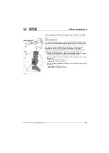
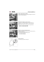
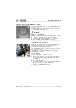
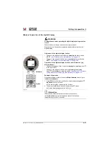
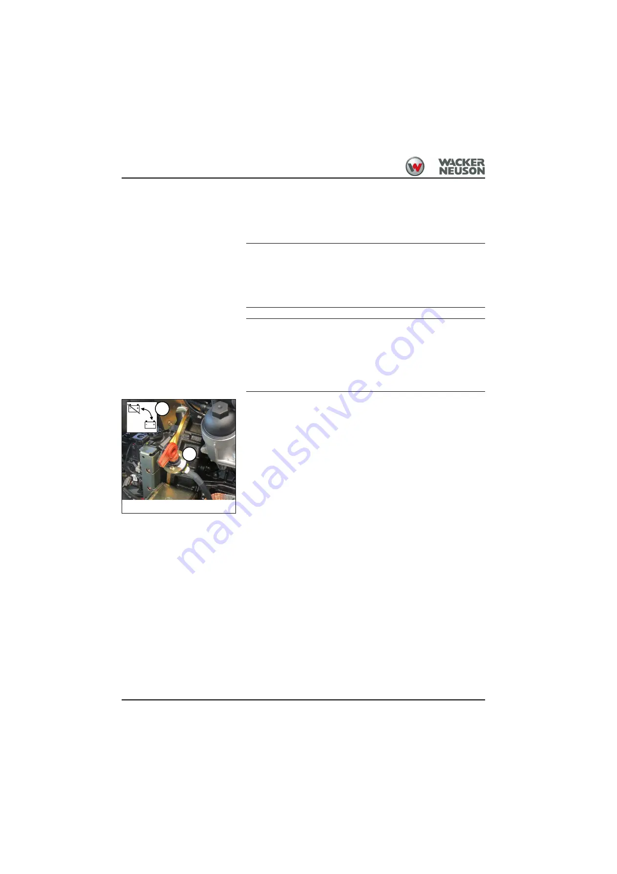
Battery master switch
The battery master switch separates the entire electrical system from the
battery and ensures protection against unauthorized engine start.
The main battery switch is located on the left in the engine compartment.
NOTICE
In order to avoid damage to the electronic elements from malfunction, do
not immediately unscrew the main battery switch from the ratchet
mechanism after shutting off the engine!
►
Note the chronological order (see the notice sign
B
)!
NOTICE
An external auxiliary heater (option) cannot be operated if the battery
master switch is removed.
►
In order to avoid damage to the auxiliary heating (optional), first
disconnect the power circuit with the battery main switch once the
after-running of the heater has ended.
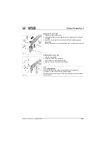
Switch off the battery master switch
1. First, stop the diesel engine with the ignition key.
2. Wait at least 30 seconds.
3. Then turn the key
A
to the left and pull out.
➥
See the notice sign
B
➥
The entire electrical system is out of operation.
Switch on the battery master switch
1. Insert the key in the battery master switch and turn it to the notched
position.
➥
The entire electrical system is in operation.
2. Start the diesel engine.
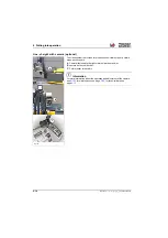
Fig. 142
A
B
Summary of Contents for 418-12
Page 59: ...BA 418 12 1 0 418_12_3_Einleitung fm 3 27 Introduction 3 Right side of machine Fig 4 30 20 ...
Page 60: ...3 28 BA 418 12 1 0 418_12_3_Einleitung fm 3 Introduction Front of machine Fig 5 ...
Page 61: ...BA 418 12 1 0 418_12_3_Einleitung fm 3 29 Introduction 3 Rear of machine Fig 6 30 20 ...
Page 63: ...BA 418 12 1 0 418_12_3_Einleitung fm 3 31 Introduction 3 Outside right of the vehicle Fig 8 ...
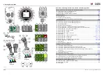
Page 64: ...3 32 BA 418 12 1 0 418_12_3_Einleitung fm 3 Introduction Inside the cabin Fig 9 ...
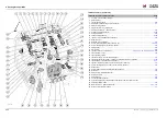
Page 65: ...BA 418 12 1 0 418_12_3_Einleitung fm 3 33 Introduction 3 Engine compartment interior Fig 10 ...
Page 66: ...3 34 BA 418 12 1 0 418_12_3_Einleitung fm 3 Introduction Outside front of the vehicle Fig 11 ...
Page 67: ...BA 418 12 1 0 418_12_3_Einleitung fm 3 35 Introduction 3 Outside rear of the vehicle Fig 12 ...
Page 326: ...5 170 BA 418 12 1 0 418_12_5_Bedienung fm 5 Operation ...
Page 338: ...6 12 BA 418 12 1 0 418_12_6_Transport fm 6 Transport ...
Page 426: ...7 88 BA 418 12 1 0 418_12_7_Wartung fm 7 Maintenance ...
Page 462: ...8 36 BA 418 12 1 0 418_12_8_Betriebsstoerung fm 8 Malfunctions Notes ...
Page 499: ...BA 418 12 1 0 BA_418_12_V1_usSIX fm S 7 Index ...
Page 500: ...S 8 BA 418 12 1 0 BA_418_12_V1_usSIX fm Index ...
Page 527: ...FORM RTF 0907 Printed in U S A ...


