BA 418-12 * 1.0 * 418_12_4_3_Bedienelemente_a4.fm
4-33
Putting into operation 4
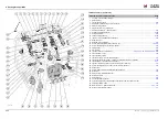
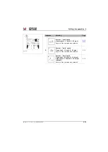
Control panels 15 – Options
Page
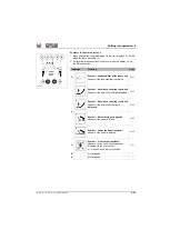
85 Touch button (green) – Load stabilizer (optional)..................................................................................
86 Push button (gray) – rotating beacon (option) .........................................................................................
87 Touch button (gray) – 14-pole front plug receptacle (option) ..................................................................
88 Touch button (gray) – 7-pole front plug receptacle 2nd circuit continuous operation (optional)..............
89 Touch button (gray) – 7-pole front plug receptacle 2nd circuit inching operation (optional)....................
90 Touch button (green) – Tipping cylinder lock (optional) ..........................................................................
91 Touch button (gray) – Reverse fan (optional)..........................................................................................
92 Touch button (gray) – 7-pole front plug receptacle 1st circuit continuous operation (optional) ...............
93 Touch button (gray) – 7-pole front plug receptacle 1st circuit inching operation (optional) ....................
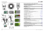
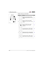
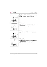
Control panels 15 – Standard
Page
94 Touch button (green) – Overload display in bucket operation.................................................................
95 Touch button (green) – Overload display in stacking operation ..............................................................
96 Touch button (green) – Overload display in manual operation................................................................
97 Button (red) – Total work hydraulics lock ................................................................................................
98 Push button (green) – continuous operation of 3rd control circuit (option)..............................................
99 Touch button (gray) – Front work light....................................................................................................
100 Touch button (gray) – Rear work light ....................................................................................................
101 Touch button (gray) – Telescopic boom work light (optional).................................................................
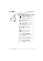
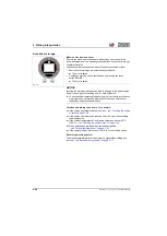
Control panels 25 – Rear attachments
Page
102 Touch button (green) – Raise the tipper (optional)...............................................................................
103 Touch button (green) – Rear auxiliary control circuit (continuous operation, right direction of rotation
(optional)...............................................................................................................................................
104 Touch button (green) – Close auto-hitch coupling (optional).................................................................
105 Touch button (green) – Unlock: three-point receptacle, PTO drive (optional) .......................................
106 Latching touch button (yellow) – Operation: PTO drive (optional).........................................................
107 Touch button (green) – Lower the tipper (optional) ..............................................................................
108 Touch button (green) – Rear auxiliary control circuit (optional)............................................................
109 Touch button (green) – Open auto-hitch coupling (optional) .................................................................
110 Touch button (green) – Floating position of the three-point receptacle (optional) ................................
111 Not assigned
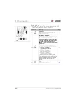
Joystick 18 – Drive, work hydraulics
Page
112 Button – Travel direction neutral (design A) ............................................................................................
113 Switch – Travel direction forwards/reverse operation (design A) ............................................................
114 Touch button – Reduce travel speed "snail“............................................................................................
115 Touch button – Increase travel speed "rabbit“.........................................................................................
116 Button – changeover valve of 3rd control circuit on the additional control circuit (option) or
14-pole plug receptacle (optional) ..................................................................................................
117 Switch – extend/retract telescopic boom .................................................................................................
118 Tip switch – bucket repositioning (option) .............................................................................................
119 Push button (gray) – differential lock ......................................................................................................
120 Rocker switch – 3rd control circuit (lock and unlock)...............................................................................
121 Latching switch – Travel direction change forwards/reverse operation (design B) .................................
122 Button – Changeover valve for 3rd control circuit (optional) (design B) ..................................................
Control elements – Three-point mount, PTO shaft drive (left vehicle rear)
Page
123 Button (yellow) – PTO shaft drive (rear) ................................................................................................
124 Button (green) – Raise three-point mount (rear) ...................................................................................
125 Button (green) – Lower three-point mount (rear)...................................................................................
Summary of Contents for 418-12
Page 59: ...BA 418 12 1 0 418_12_3_Einleitung fm 3 27 Introduction 3 Right side of machine Fig 4 30 20 ...
Page 60: ...3 28 BA 418 12 1 0 418_12_3_Einleitung fm 3 Introduction Front of machine Fig 5 ...
Page 61: ...BA 418 12 1 0 418_12_3_Einleitung fm 3 29 Introduction 3 Rear of machine Fig 6 30 20 ...
Page 63: ...BA 418 12 1 0 418_12_3_Einleitung fm 3 31 Introduction 3 Outside right of the vehicle Fig 8 ...
Page 64: ...3 32 BA 418 12 1 0 418_12_3_Einleitung fm 3 Introduction Inside the cabin Fig 9 ...
Page 65: ...BA 418 12 1 0 418_12_3_Einleitung fm 3 33 Introduction 3 Engine compartment interior Fig 10 ...
Page 66: ...3 34 BA 418 12 1 0 418_12_3_Einleitung fm 3 Introduction Outside front of the vehicle Fig 11 ...
Page 67: ...BA 418 12 1 0 418_12_3_Einleitung fm 3 35 Introduction 3 Outside rear of the vehicle Fig 12 ...
Page 326: ...5 170 BA 418 12 1 0 418_12_5_Bedienung fm 5 Operation ...
Page 338: ...6 12 BA 418 12 1 0 418_12_6_Transport fm 6 Transport ...
Page 426: ...7 88 BA 418 12 1 0 418_12_7_Wartung fm 7 Maintenance ...
Page 462: ...8 36 BA 418 12 1 0 418_12_8_Betriebsstoerung fm 8 Malfunctions Notes ...
Page 499: ...BA 418 12 1 0 BA_418_12_V1_usSIX fm S 7 Index ...
Page 500: ...S 8 BA 418 12 1 0 BA_418_12_V1_usSIX fm Index ...
Page 527: ...FORM RTF 0907 Printed in U S A ...

