4-34
BA 418-12 * 1.0 * 418_12_4_4_Inbetriebnahme.fm
4 Putting into operation
4.3
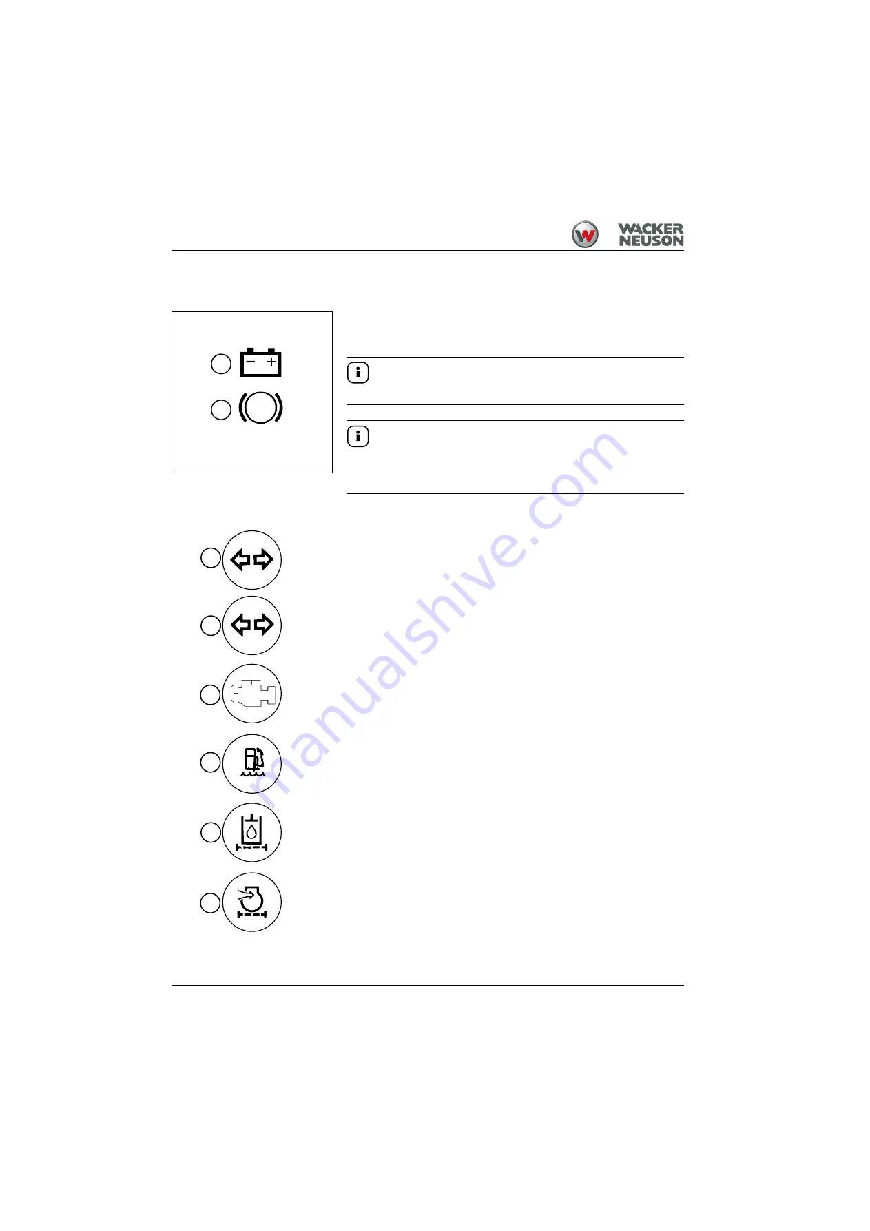
Overview of indicator lights
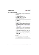
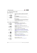
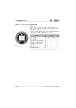
Indicator light check
When the ignition is switched on, all indicator lights on the indicating
instrument illuminate briefly for a check and then go out after a few
seconds.
Information
Indicator lights
and
remain lit when ignition is turned on!
Information
For your own safety and in order to avoid consequential damage to the
machine, have malfunctioning indicator lights immediately checked or
replaced by an authorized service center!
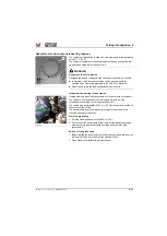
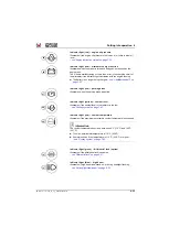
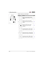
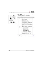
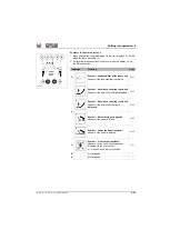
Indicator lights on indicating instrument
Indicator light (green) – right/left turn indicator
Flashes intermittently when the direction indicators are used
– see "Turn indicators" on page 5-28
.
Indicator light (green) – right/left turn indicators on rear
attachment
Flashes intermittently when the turn indicators are used and a front or rear
attachment is connected electrically.
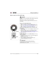
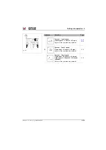
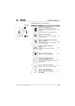
Indicator light (yellow) – control unit/controller
Illuminates if an error comes from the engine controller or the cabin
controller
– see chapter 8 " Overview of error codes of diesel engine
and
“Overview of error codes of drive electronics”
.
Indicator light (red) – fuel system water separator (option)
Illuminates if there is too much water in the water separator of the fuel
pre-filter:
Drain water
– see "Fuel system" on page 7-35
Indicator light (red) – dirt in hydraulic oil filter
Illuminates if the resistance of the oil flow in the return filter is too high
– see "Monitoring the hydraulic oil filter" on page 7-55
Indicator light (yellow) – air filter
Illuminates if the air filter is dirty
– see "Air filter" on page 7-49
Fig. 148
P
1
Summary of Contents for 418-12
Page 59: ...BA 418 12 1 0 418_12_3_Einleitung fm 3 27 Introduction 3 Right side of machine Fig 4 30 20 ...
Page 60: ...3 28 BA 418 12 1 0 418_12_3_Einleitung fm 3 Introduction Front of machine Fig 5 ...
Page 61: ...BA 418 12 1 0 418_12_3_Einleitung fm 3 29 Introduction 3 Rear of machine Fig 6 30 20 ...
Page 63: ...BA 418 12 1 0 418_12_3_Einleitung fm 3 31 Introduction 3 Outside right of the vehicle Fig 8 ...
Page 64: ...3 32 BA 418 12 1 0 418_12_3_Einleitung fm 3 Introduction Inside the cabin Fig 9 ...
Page 65: ...BA 418 12 1 0 418_12_3_Einleitung fm 3 33 Introduction 3 Engine compartment interior Fig 10 ...
Page 66: ...3 34 BA 418 12 1 0 418_12_3_Einleitung fm 3 Introduction Outside front of the vehicle Fig 11 ...
Page 67: ...BA 418 12 1 0 418_12_3_Einleitung fm 3 35 Introduction 3 Outside rear of the vehicle Fig 12 ...
Page 326: ...5 170 BA 418 12 1 0 418_12_5_Bedienung fm 5 Operation ...
Page 338: ...6 12 BA 418 12 1 0 418_12_6_Transport fm 6 Transport ...
Page 426: ...7 88 BA 418 12 1 0 418_12_7_Wartung fm 7 Maintenance ...
Page 462: ...8 36 BA 418 12 1 0 418_12_8_Betriebsstoerung fm 8 Malfunctions Notes ...
Page 499: ...BA 418 12 1 0 BA_418_12_V1_usSIX fm S 7 Index ...
Page 500: ...S 8 BA 418 12 1 0 BA_418_12_V1_usSIX fm Index ...
Page 527: ...FORM RTF 0907 Printed in U S A ...

