4-40
BA 418-12 * 1.0 * 418_12_4_4_Inbetriebnahme.fm
4 Putting into operation
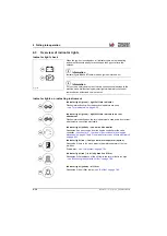
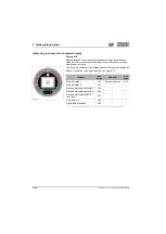
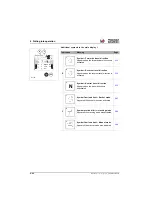
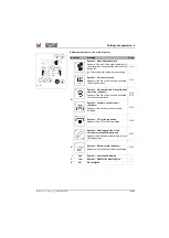
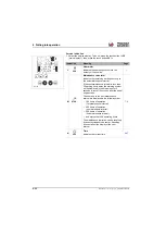
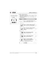
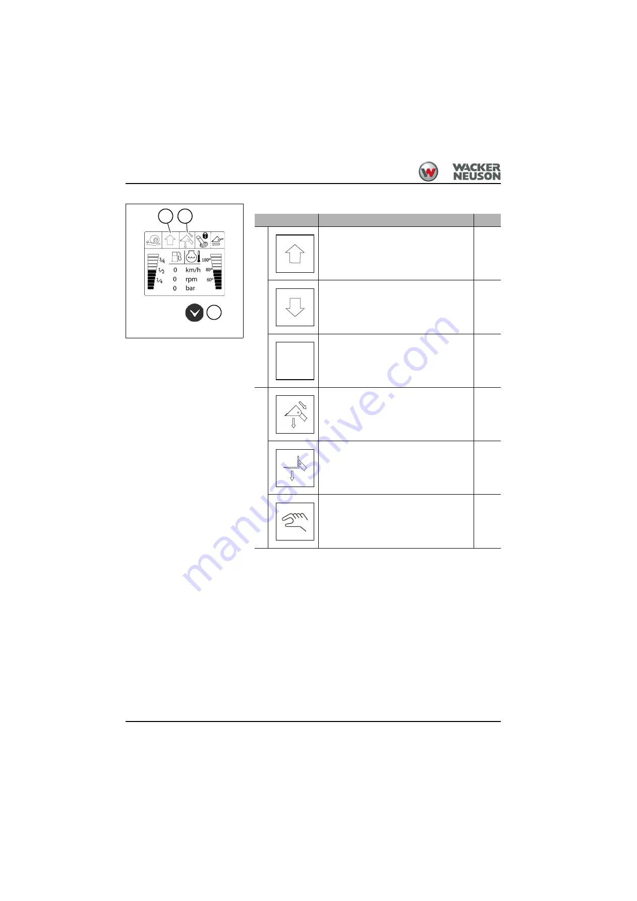
Additional symbols in the main display 1
Fig. 153
E
F
Indication
Meaning
Page
E
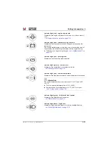
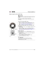
Symbol – Forwards travel direction
Appears when the forwards travel direction is
activated
Symbol – Reverse travel direction
Appears when the reverse travel direction is
activated
Symbol – Neutral travel direction
Appears when the travel direction is
deactivated
F
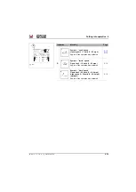
Symbol Overload limit – Bucket mode
Appears if the bucket mode was activated
Symbol overload limit – stacking mode
Appears if the stacking mode was activated
Symbol Overload limit – Manual mode
Appears if the manual mode was activated
1
2
N
3
1
2
3
Summary of Contents for 418-12
Page 59: ...BA 418 12 1 0 418_12_3_Einleitung fm 3 27 Introduction 3 Right side of machine Fig 4 30 20 ...
Page 60: ...3 28 BA 418 12 1 0 418_12_3_Einleitung fm 3 Introduction Front of machine Fig 5 ...
Page 61: ...BA 418 12 1 0 418_12_3_Einleitung fm 3 29 Introduction 3 Rear of machine Fig 6 30 20 ...
Page 63: ...BA 418 12 1 0 418_12_3_Einleitung fm 3 31 Introduction 3 Outside right of the vehicle Fig 8 ...
Page 64: ...3 32 BA 418 12 1 0 418_12_3_Einleitung fm 3 Introduction Inside the cabin Fig 9 ...
Page 65: ...BA 418 12 1 0 418_12_3_Einleitung fm 3 33 Introduction 3 Engine compartment interior Fig 10 ...
Page 66: ...3 34 BA 418 12 1 0 418_12_3_Einleitung fm 3 Introduction Outside front of the vehicle Fig 11 ...
Page 67: ...BA 418 12 1 0 418_12_3_Einleitung fm 3 35 Introduction 3 Outside rear of the vehicle Fig 12 ...
Page 326: ...5 170 BA 418 12 1 0 418_12_5_Bedienung fm 5 Operation ...
Page 338: ...6 12 BA 418 12 1 0 418_12_6_Transport fm 6 Transport ...
Page 426: ...7 88 BA 418 12 1 0 418_12_7_Wartung fm 7 Maintenance ...
Page 462: ...8 36 BA 418 12 1 0 418_12_8_Betriebsstoerung fm 8 Malfunctions Notes ...
Page 499: ...BA 418 12 1 0 BA_418_12_V1_usSIX fm S 7 Index ...
Page 500: ...S 8 BA 418 12 1 0 BA_418_12_V1_usSIX fm Index ...
Page 527: ...FORM RTF 0907 Printed in U S A ...

