BA 418-12 * 1.0 * 418_12_5_Bedienung.fm
5-45
Operation 5
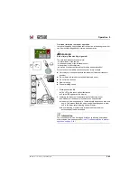
“Smart Handling” overload control
Description / function
The "Smart Handling" overload limitation prevents the extended telescopic
loader unit from entering into the overload range when lowering, thereby
preventing the vehicle from tipping forward.
This ensures that the permissible operating range of the load-bearing
capacity diagram is observed.
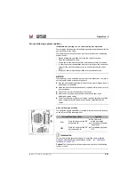
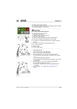
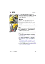
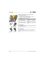
The overload control has 3 operating modes:
• Bucker operation: button
/ symbol
F/1
– see "Overload control in bucket mode" on page 5-47
.
• Stacking operation: button
/ symbol
F/2
– see "Overload control in fork-lift mode" on page 5-48
.
• Manual operation: button
/ symbol
F/3
– see "Overload limitation in manual operation" on page 5-49
In bucket mode
• Automatic reduced lowering speed depending on load and angle.
• Automatic boom retraction
In fork-lift mode
• Nearly vertical raising and lowering.
• Automatic reduced lowering speed depending on load and angle.
• Automatic retraction of the telescopic boom when lowering and
automatic extension of the telescopic boom when lifting
• The telescopic boom can be overridden on the joystick when extending
with the roller
➥
If the machine is put in the overload range by extending the
telescopic boom with the scroll wheel, the overload control
automatically switches off boom extension.
In manual operation
• All loader unit and boom movements can be performed.
• Automatic reduced lowering speed depending on load and angle.
Lowering speed is reduced to standstill in doing so.
• Boom extension is switched off in case of overload
.
Fig. 226
1
2
3
F
Summary of Contents for 418-12
Page 59: ...BA 418 12 1 0 418_12_3_Einleitung fm 3 27 Introduction 3 Right side of machine Fig 4 30 20 ...
Page 60: ...3 28 BA 418 12 1 0 418_12_3_Einleitung fm 3 Introduction Front of machine Fig 5 ...
Page 61: ...BA 418 12 1 0 418_12_3_Einleitung fm 3 29 Introduction 3 Rear of machine Fig 6 30 20 ...
Page 63: ...BA 418 12 1 0 418_12_3_Einleitung fm 3 31 Introduction 3 Outside right of the vehicle Fig 8 ...
Page 64: ...3 32 BA 418 12 1 0 418_12_3_Einleitung fm 3 Introduction Inside the cabin Fig 9 ...
Page 65: ...BA 418 12 1 0 418_12_3_Einleitung fm 3 33 Introduction 3 Engine compartment interior Fig 10 ...
Page 66: ...3 34 BA 418 12 1 0 418_12_3_Einleitung fm 3 Introduction Outside front of the vehicle Fig 11 ...
Page 67: ...BA 418 12 1 0 418_12_3_Einleitung fm 3 35 Introduction 3 Outside rear of the vehicle Fig 12 ...
Page 326: ...5 170 BA 418 12 1 0 418_12_5_Bedienung fm 5 Operation ...
Page 338: ...6 12 BA 418 12 1 0 418_12_6_Transport fm 6 Transport ...
Page 426: ...7 88 BA 418 12 1 0 418_12_7_Wartung fm 7 Maintenance ...
Page 462: ...8 36 BA 418 12 1 0 418_12_8_Betriebsstoerung fm 8 Malfunctions Notes ...
Page 499: ...BA 418 12 1 0 BA_418_12_V1_usSIX fm S 7 Index ...
Page 500: ...S 8 BA 418 12 1 0 BA_418_12_V1_usSIX fm Index ...
Page 527: ...FORM RTF 0907 Printed in U S A ...

