5-54
BA 418-12 * 1.0 * 418_12_5_Bedienung.fm
5 Operation
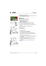
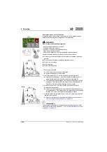
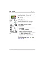
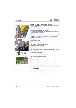
Unlocking/locking an attachment to the quickhitch facility
Information
The attachment locked in the quickhitch facility is secured against
unintentional unlocking for safety reasons.
The attachment can only be unlocked by pressing
push button and
switch
on the joystick
with both hands
at the same time. The
operator must be seated on the seat for this.
►
The button
for unlocking is located in the switch console on the left
beside the steering wheel.
NOTICE
In order to avoid damage to the attachment lock due to an attachment that
is not fully unlocked, follow the order of unlocking.
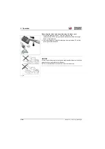
Unlocking the attachment
1. Disable the road-travel lock of the work hydraulics if it is enabled. To
do this: press the button
.
➥
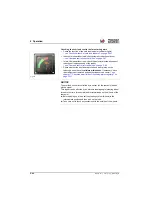
Symbol
G/1
disappears in the display.
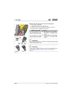
2. Unlock the attachment. To do so, press the touch button
down into
position
A
and hold.
3. Press the rocker switch
to the
right (B)
(seen in the travel
direction) at the same time until the lock bolts are driven fully out of the
center bores of the attachment.
➥
Symbol
G/2
appears in the digital display
4. First release the switch
, then release the button
➥
Symbol
G/2
goes out in the digital display
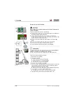
Locking the attachment
1. After picking up an attachment with the quick-hitch device, press
rocker switch
to the left (A)
in the travel direction.
➥
The attachment is locked in the quickhitch.
2. Enable the road-travel lock during machine travel on public roads. To
do this: press push button
➥
Symbol
G/1
appears in the digital display of the indicator.
➥
The LED in the push button illuminates.
➥
Switch
on the joystick is not functional.
Fig. 237
B
A
A
1
2
Summary of Contents for 418-12
Page 59: ...BA 418 12 1 0 418_12_3_Einleitung fm 3 27 Introduction 3 Right side of machine Fig 4 30 20 ...
Page 60: ...3 28 BA 418 12 1 0 418_12_3_Einleitung fm 3 Introduction Front of machine Fig 5 ...
Page 61: ...BA 418 12 1 0 418_12_3_Einleitung fm 3 29 Introduction 3 Rear of machine Fig 6 30 20 ...
Page 63: ...BA 418 12 1 0 418_12_3_Einleitung fm 3 31 Introduction 3 Outside right of the vehicle Fig 8 ...
Page 64: ...3 32 BA 418 12 1 0 418_12_3_Einleitung fm 3 Introduction Inside the cabin Fig 9 ...
Page 65: ...BA 418 12 1 0 418_12_3_Einleitung fm 3 33 Introduction 3 Engine compartment interior Fig 10 ...
Page 66: ...3 34 BA 418 12 1 0 418_12_3_Einleitung fm 3 Introduction Outside front of the vehicle Fig 11 ...
Page 67: ...BA 418 12 1 0 418_12_3_Einleitung fm 3 35 Introduction 3 Outside rear of the vehicle Fig 12 ...
Page 326: ...5 170 BA 418 12 1 0 418_12_5_Bedienung fm 5 Operation ...
Page 338: ...6 12 BA 418 12 1 0 418_12_6_Transport fm 6 Transport ...
Page 426: ...7 88 BA 418 12 1 0 418_12_7_Wartung fm 7 Maintenance ...
Page 462: ...8 36 BA 418 12 1 0 418_12_8_Betriebsstoerung fm 8 Malfunctions Notes ...
Page 499: ...BA 418 12 1 0 BA_418_12_V1_usSIX fm S 7 Index ...
Page 500: ...S 8 BA 418 12 1 0 BA_418_12_V1_usSIX fm Index ...
Page 527: ...FORM RTF 0907 Printed in U S A ...

