5-70
BA 418-12 * 1.0 * 418_12_5_Bedienung.fm
5 Operation
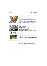
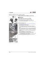
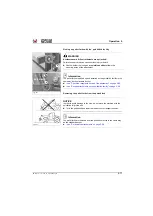
Pressure release of the flat connector plugs of the 3rd control circuit (standard)
Information
The hydraulic system of the machine is still pressurized even when the
engine is not running!
The hydraulic plug couplings can be released, however they cannot
be re-attached because the pressure in the hydraulic lines has not been
released.
►
Release the pressure in the system sections before installing or
removing an attachment!
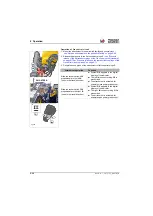
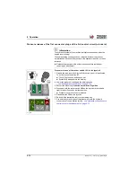
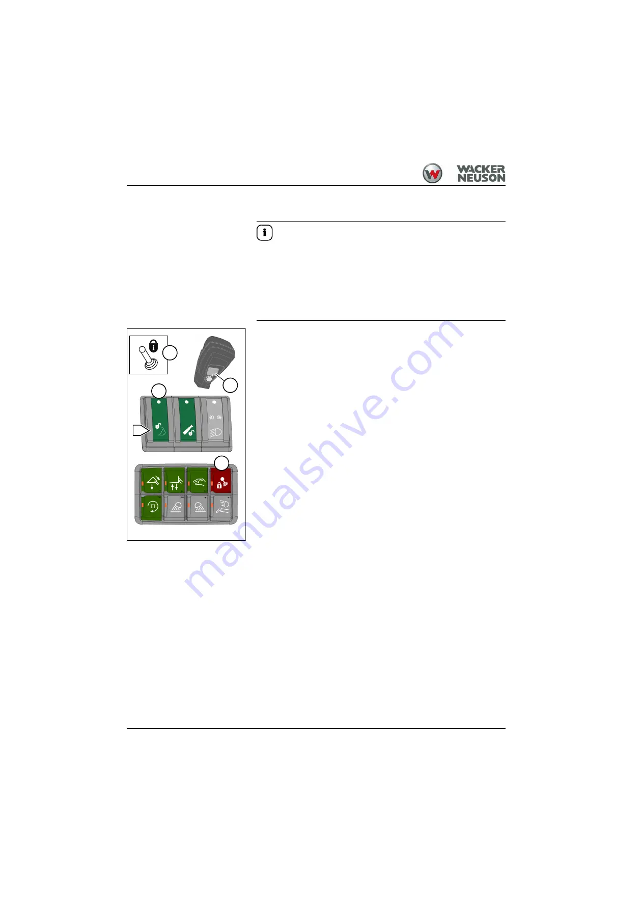
Pressure release of the rocker switch 120 in the joystick
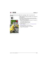
1. Disable the road-travel lock for the 3rd control circuit if it is activated.
To do this: press the button
➥
The LED in the push button goes out.
➥
Symbol
G/1
disappears in the display.
2. Lower the loader unit and apply the parking brake
– see "Parking brake (hand brake)" on page 5-12
3. Shut off the diesel engine
but do not switch off ignition
.
4. Press and hold the rocker switch
on the joystick to the left and
right for about 5 seconds in either position.
➥
Pressure in hydraulic lines is released.
5. Release switch
on the joystick.
6. Switch off the starter and remove the starting key.
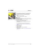
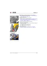
7. Connect the hydraulic lines of the attachment onto the hydraulic
connections of the quickhitch facility
– see "Hydraulic connections: 3rd
control circuit to the attachment" on page 5-72
.
Fig. 255
A
1
Summary of Contents for 418-12
Page 59: ...BA 418 12 1 0 418_12_3_Einleitung fm 3 27 Introduction 3 Right side of machine Fig 4 30 20 ...
Page 60: ...3 28 BA 418 12 1 0 418_12_3_Einleitung fm 3 Introduction Front of machine Fig 5 ...
Page 61: ...BA 418 12 1 0 418_12_3_Einleitung fm 3 29 Introduction 3 Rear of machine Fig 6 30 20 ...
Page 63: ...BA 418 12 1 0 418_12_3_Einleitung fm 3 31 Introduction 3 Outside right of the vehicle Fig 8 ...
Page 64: ...3 32 BA 418 12 1 0 418_12_3_Einleitung fm 3 Introduction Inside the cabin Fig 9 ...
Page 65: ...BA 418 12 1 0 418_12_3_Einleitung fm 3 33 Introduction 3 Engine compartment interior Fig 10 ...
Page 66: ...3 34 BA 418 12 1 0 418_12_3_Einleitung fm 3 Introduction Outside front of the vehicle Fig 11 ...
Page 67: ...BA 418 12 1 0 418_12_3_Einleitung fm 3 35 Introduction 3 Outside rear of the vehicle Fig 12 ...
Page 326: ...5 170 BA 418 12 1 0 418_12_5_Bedienung fm 5 Operation ...
Page 338: ...6 12 BA 418 12 1 0 418_12_6_Transport fm 6 Transport ...
Page 426: ...7 88 BA 418 12 1 0 418_12_7_Wartung fm 7 Maintenance ...
Page 462: ...8 36 BA 418 12 1 0 418_12_8_Betriebsstoerung fm 8 Malfunctions Notes ...
Page 499: ...BA 418 12 1 0 BA_418_12_V1_usSIX fm S 7 Index ...
Page 500: ...S 8 BA 418 12 1 0 BA_418_12_V1_usSIX fm Index ...
Page 527: ...FORM RTF 0907 Printed in U S A ...

