BA 418-12 * 1.0 * 418_12_5_Bedienung.fm
5-85
Operation 5
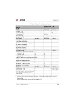
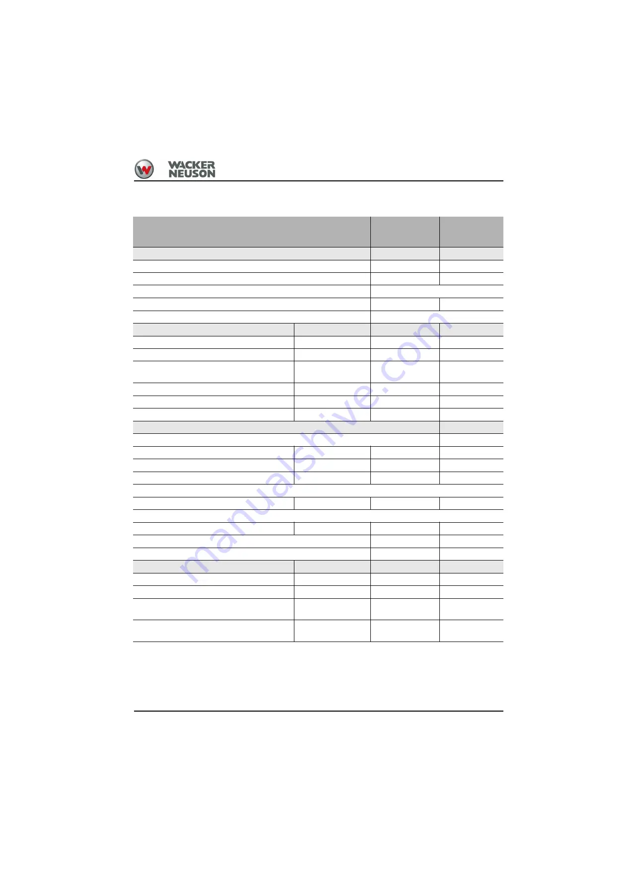
Example: Test plan for third party attachments
Machine model:
Serial no.:
Job no.:
Attachment type:
Attachment no.:
Date:
Tester:
Stability
Actual value
Remarks
Wheelbase [mm]
Front left wheel [N]
[N]
Front right wheel [N]
Front axle =
Rear left wheel [N]
Rear right wheel [N]
Rear axle =
Technical data
Specified
Actual value
Remarks
Tilt-in angle (lower position)
Tilt-out angle (upper position)
Distance between center of gravity of payload
and center of front axle [mm]
Capacity as per type label [l]
Gamma as per type label
Weight of attachment [kg]
1
Attachment functions
Remarks
Hitching the attachment onto the wheel loader
Mechanically OK
Yes
No
Hydraulically OK
Yes
No
Electrically OK
Yes
No
Mechanical stops (tilt out/tilt in) existing and functional
OK
Yes
No
Hose routing (length, damage, age)
OK
Yes
No
Nominal width of pressure line [mm]
10
Nominal width of return line [mm]
10
Pressures
Specified
Actual value
Remarks
At idling speed
[bar]
Oil 50°C (122°F)
Under full load
[bar]
Oil 50°C (122°F)
Permissible hydraulic pressures not exceeded
at nominal load of boundary states [bar]
Other remarks:
1.
With the three-point mount option, the max. permissible gross weight rating and the max. permissible rear axle load should not
be exceeded. See
Only under the prerequisite that at least 20% of the actually present gross weight rating is allotted to the front axle. Otherwise the vehicle is considered
"incapable of steering!"
The front can additionally be ballasted in compliance with the aforementioned requirements.
Summary of Contents for 418-12
Page 59: ...BA 418 12 1 0 418_12_3_Einleitung fm 3 27 Introduction 3 Right side of machine Fig 4 30 20 ...
Page 60: ...3 28 BA 418 12 1 0 418_12_3_Einleitung fm 3 Introduction Front of machine Fig 5 ...
Page 61: ...BA 418 12 1 0 418_12_3_Einleitung fm 3 29 Introduction 3 Rear of machine Fig 6 30 20 ...
Page 63: ...BA 418 12 1 0 418_12_3_Einleitung fm 3 31 Introduction 3 Outside right of the vehicle Fig 8 ...
Page 64: ...3 32 BA 418 12 1 0 418_12_3_Einleitung fm 3 Introduction Inside the cabin Fig 9 ...
Page 65: ...BA 418 12 1 0 418_12_3_Einleitung fm 3 33 Introduction 3 Engine compartment interior Fig 10 ...
Page 66: ...3 34 BA 418 12 1 0 418_12_3_Einleitung fm 3 Introduction Outside front of the vehicle Fig 11 ...
Page 67: ...BA 418 12 1 0 418_12_3_Einleitung fm 3 35 Introduction 3 Outside rear of the vehicle Fig 12 ...
Page 326: ...5 170 BA 418 12 1 0 418_12_5_Bedienung fm 5 Operation ...
Page 338: ...6 12 BA 418 12 1 0 418_12_6_Transport fm 6 Transport ...
Page 426: ...7 88 BA 418 12 1 0 418_12_7_Wartung fm 7 Maintenance ...
Page 462: ...8 36 BA 418 12 1 0 418_12_8_Betriebsstoerung fm 8 Malfunctions Notes ...
Page 499: ...BA 418 12 1 0 BA_418_12_V1_usSIX fm S 7 Index ...
Page 500: ...S 8 BA 418 12 1 0 BA_418_12_V1_usSIX fm Index ...
Page 527: ...FORM RTF 0907 Printed in U S A ...

