BA 418-12 * 1.0 * 418_12_5_Bedienung.fm
5-103
Operation 5
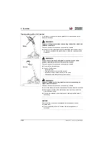
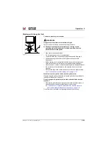
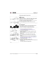
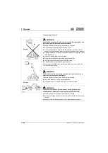
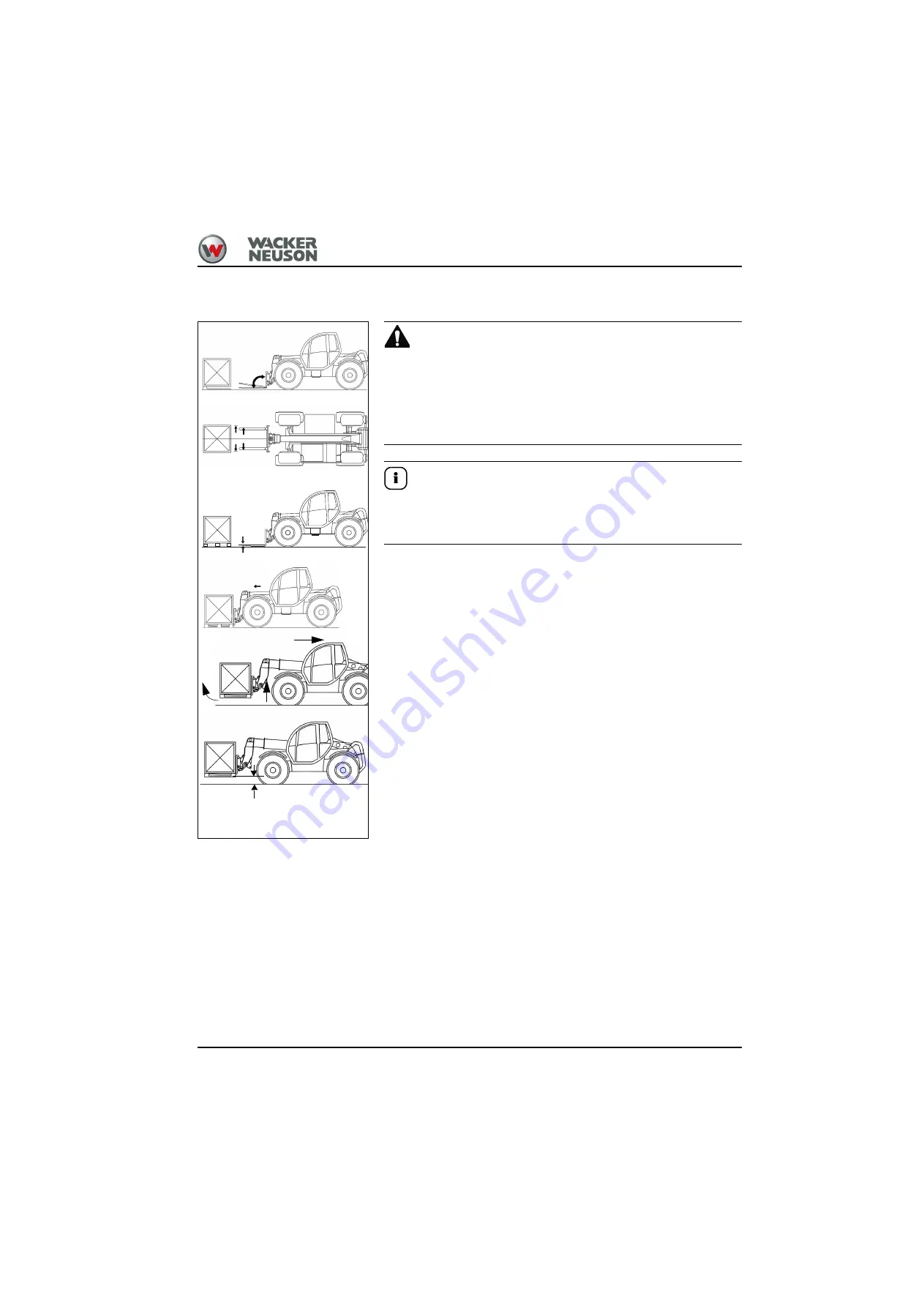
Picking up material with the pallet forks
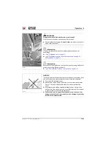
WARNING
Danger of accident due to restricted line-of-sight during transport!
Failure to observe this can cause serious injury or death.
►
Transport the cargo in the transport position about 175 mm ( 6.8 in).
►
Check the line of sight and adjust the mirrors.
►
If the line-of-sight cannot be ensured, use the camera option.
Information
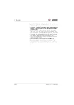
The telescopic boom yields easily with the load stabilizer switched on,
making it difficult to perform any precise lifting movements.
►
Switch off the load stabilizer during pallet forks operation!
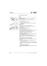
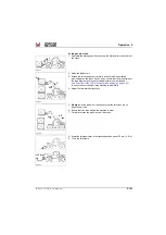
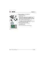
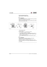
1. Switch off the load stabilizer before starting work
– see "Load stabilizer for loader unit (option)" on page 5-121
.
2. Fully retract the telescopic boom.
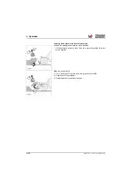
3. Stop the telehandler right before the load and align the fork tines
parallel to the ground.
4. Adjust the distance of the fork tines with regard to the center line
(dashed line).
5. Raise the loader unit until the pallet can be picked up easily.
6. Move carefully forward until the fork frame is in contact with the
material.
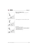
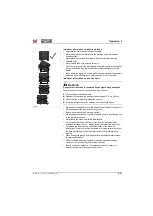
7. Raise the loader unit and ensure that the limits of load diagram and
overload warning device are not exceeded
LED´s in the overload display" on page 5-39
!
8. Tilt the fork frame backward.
9. Ensure that the area behind the machine is clear.
10.Reverse the vehicle carefully until the loader unit can be lowered to the
transport position.
➥
Transport position about
175 mm (6.8 in)
3.
4.
5.
6.
8.
7.
Fig. 292
175 mm
10.
Summary of Contents for 418-12
Page 59: ...BA 418 12 1 0 418_12_3_Einleitung fm 3 27 Introduction 3 Right side of machine Fig 4 30 20 ...
Page 60: ...3 28 BA 418 12 1 0 418_12_3_Einleitung fm 3 Introduction Front of machine Fig 5 ...
Page 61: ...BA 418 12 1 0 418_12_3_Einleitung fm 3 29 Introduction 3 Rear of machine Fig 6 30 20 ...
Page 63: ...BA 418 12 1 0 418_12_3_Einleitung fm 3 31 Introduction 3 Outside right of the vehicle Fig 8 ...
Page 64: ...3 32 BA 418 12 1 0 418_12_3_Einleitung fm 3 Introduction Inside the cabin Fig 9 ...
Page 65: ...BA 418 12 1 0 418_12_3_Einleitung fm 3 33 Introduction 3 Engine compartment interior Fig 10 ...
Page 66: ...3 34 BA 418 12 1 0 418_12_3_Einleitung fm 3 Introduction Outside front of the vehicle Fig 11 ...
Page 67: ...BA 418 12 1 0 418_12_3_Einleitung fm 3 35 Introduction 3 Outside rear of the vehicle Fig 12 ...
Page 326: ...5 170 BA 418 12 1 0 418_12_5_Bedienung fm 5 Operation ...
Page 338: ...6 12 BA 418 12 1 0 418_12_6_Transport fm 6 Transport ...
Page 426: ...7 88 BA 418 12 1 0 418_12_7_Wartung fm 7 Maintenance ...
Page 462: ...8 36 BA 418 12 1 0 418_12_8_Betriebsstoerung fm 8 Malfunctions Notes ...
Page 499: ...BA 418 12 1 0 BA_418_12_V1_usSIX fm S 7 Index ...
Page 500: ...S 8 BA 418 12 1 0 BA_418_12_V1_usSIX fm Index ...
Page 527: ...FORM RTF 0907 Printed in U S A ...

