5-140
BA 418-12 * 1.0 * 418_12_5_Bedienung.fm
5 Operation
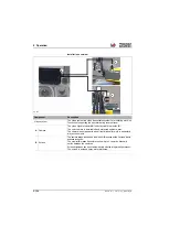
Bucket repositioning (option)
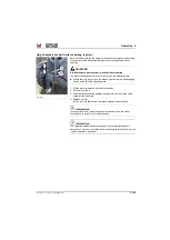
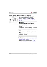
With the automatic bucket return, cyclical work, such as loading a truck,
can be performed rationally and in a manner that saves material.
This option makes it possible to save any tilt angle of the tilt ram and to
apply it by pressing a push button (horizontal bucket position during work
operation, for example).
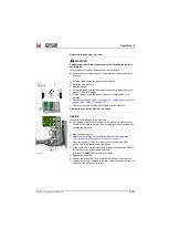
Put the automatic bucket return into operation
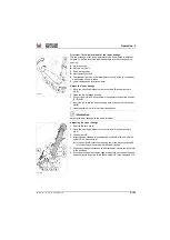
Example for loading operation with bucket repositioning:
1. Lower the bucket with the joystick and align this horizontally with the
ground
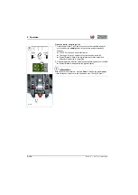
2. Save the selected alignment
A
(tilt angle) of the loader bucket. To do
this, press and hold down the button
(joystick)
for 3 seconds
➥
The beep signal sounds and the symbol
H/1
appears in the digital
display
➥
The selected tilt angle
A
is saved.
3. Fill the bucket with the loaded material in forward travel. To do this, tilt
the bucket in and lift it slightly at the same time.
4. Drive backwards and dump out the loaded material at the unloading
point.
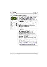
5. Pick up the new load material. To do this, lower the loader unit in the
forward direction and briefly press the button
➥
The bucket is automatically adjusted to the saved tilting angle
A
.
➥
The symbol
appears in the digital display
6. Picking up a load
Information
The tilt angle remains permanently until the bucket is not manually tilted in
or emptied.
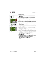
►
The automatic bucket return is disrupted with the tilt in or empty shovel
of the loader bucket, but can be reactivated by pressing the button
again.
►
The saved tilt angle can be accessed at the touch of a push button if
necessary and can be overwritten at any time with a new tilt angle.
►
With the ignition switched off or restart of the diesel engine, the saved
tilt angle setting is deleted and must be reset again when starting the
diesel engine and saved.
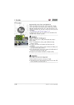
Fig. 333
1
A
Summary of Contents for 418-12
Page 59: ...BA 418 12 1 0 418_12_3_Einleitung fm 3 27 Introduction 3 Right side of machine Fig 4 30 20 ...
Page 60: ...3 28 BA 418 12 1 0 418_12_3_Einleitung fm 3 Introduction Front of machine Fig 5 ...
Page 61: ...BA 418 12 1 0 418_12_3_Einleitung fm 3 29 Introduction 3 Rear of machine Fig 6 30 20 ...
Page 63: ...BA 418 12 1 0 418_12_3_Einleitung fm 3 31 Introduction 3 Outside right of the vehicle Fig 8 ...
Page 64: ...3 32 BA 418 12 1 0 418_12_3_Einleitung fm 3 Introduction Inside the cabin Fig 9 ...
Page 65: ...BA 418 12 1 0 418_12_3_Einleitung fm 3 33 Introduction 3 Engine compartment interior Fig 10 ...
Page 66: ...3 34 BA 418 12 1 0 418_12_3_Einleitung fm 3 Introduction Outside front of the vehicle Fig 11 ...
Page 67: ...BA 418 12 1 0 418_12_3_Einleitung fm 3 35 Introduction 3 Outside rear of the vehicle Fig 12 ...
Page 326: ...5 170 BA 418 12 1 0 418_12_5_Bedienung fm 5 Operation ...
Page 338: ...6 12 BA 418 12 1 0 418_12_6_Transport fm 6 Transport ...
Page 426: ...7 88 BA 418 12 1 0 418_12_7_Wartung fm 7 Maintenance ...
Page 462: ...8 36 BA 418 12 1 0 418_12_8_Betriebsstoerung fm 8 Malfunctions Notes ...
Page 499: ...BA 418 12 1 0 BA_418_12_V1_usSIX fm S 7 Index ...
Page 500: ...S 8 BA 418 12 1 0 BA_418_12_V1_usSIX fm Index ...
Page 527: ...FORM RTF 0907 Printed in U S A ...


