5-142
BA 418-12 * 1.0 * 418_12_5_Bedienung.fm
5 Operation
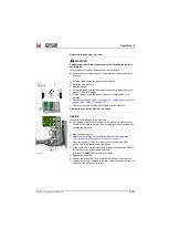
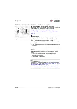
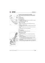
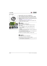
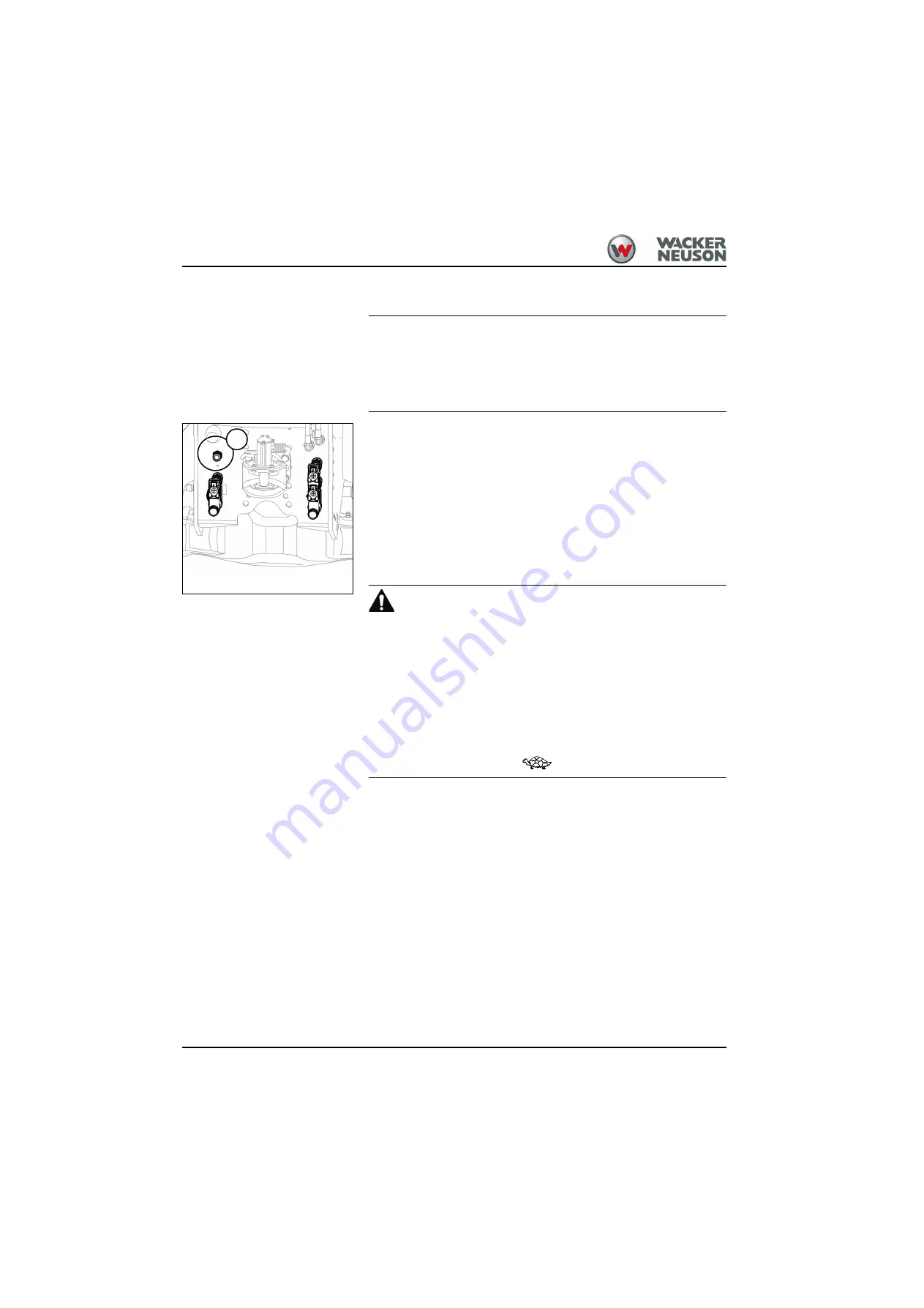
Coupling a trailer brake hose
NOTICE
Clean the plug coupling carefully before connecting the flexible line of the
trailer in order to ensure correct functioning and sealing!
►
Inspection and maintenance work on the hydraulic brake may be
performed only by trained personnel or an authorized service center.
1. Attach trailer to the ball hitch
– see "Coupling a trailer" on page 5-126
.
2. Clean the brake hose and quick coupler
D
.
3. Couple the brake hose onto quick coupler
D
.
4. Establish the electric and hydraulic connections between the trailer
and the tractor vehicle.
5. Remove the wheel chocks from the wheels of the trailer and safely
store them on the trailer.
6. Release the trailer brake.
➥
Refer to the Operator’s Manual of the trailer.
Performing machine travel with the hydraulic trailer brake
WARNING
Performing machine travel too fast can cause serious accidents!
The trailer brake can overheat on longer downhill stretches with the
brake/inching pedal pressed only halfway through!
Failure to observe this can cause serious injury or death.
►
Reduce the travel speed early enough before turning or downhill
machine travel.
►
Reduce engine speed: remove your foot from the accelerator pedal.
►
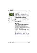
Brake the vehicle by braking intermittently. To do this: briefly press the
brake-inch pedal several times through the inch range.
►
Select the next lower speed
.
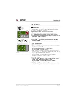
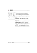
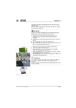
When braking the vehicle with the brake/inching pedal
oil pressure is
fed into the hydraulic trailer braking system and the trailer is braked.
The parking brake has no effect on the trailer braking system.
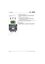
If the travel speed is reduced with brake-inch pedal
, oil pressure is
applied to the trailer braking system after about 20 % of the pedal travel.
This “advance action” slightly brakes the trailer, and the tractor-trailer
combination is held in a taut line.
Fig. 335
D
Summary of Contents for 418-12
Page 59: ...BA 418 12 1 0 418_12_3_Einleitung fm 3 27 Introduction 3 Right side of machine Fig 4 30 20 ...
Page 60: ...3 28 BA 418 12 1 0 418_12_3_Einleitung fm 3 Introduction Front of machine Fig 5 ...
Page 61: ...BA 418 12 1 0 418_12_3_Einleitung fm 3 29 Introduction 3 Rear of machine Fig 6 30 20 ...
Page 63: ...BA 418 12 1 0 418_12_3_Einleitung fm 3 31 Introduction 3 Outside right of the vehicle Fig 8 ...
Page 64: ...3 32 BA 418 12 1 0 418_12_3_Einleitung fm 3 Introduction Inside the cabin Fig 9 ...
Page 65: ...BA 418 12 1 0 418_12_3_Einleitung fm 3 33 Introduction 3 Engine compartment interior Fig 10 ...
Page 66: ...3 34 BA 418 12 1 0 418_12_3_Einleitung fm 3 Introduction Outside front of the vehicle Fig 11 ...
Page 67: ...BA 418 12 1 0 418_12_3_Einleitung fm 3 35 Introduction 3 Outside rear of the vehicle Fig 12 ...
Page 326: ...5 170 BA 418 12 1 0 418_12_5_Bedienung fm 5 Operation ...
Page 338: ...6 12 BA 418 12 1 0 418_12_6_Transport fm 6 Transport ...
Page 426: ...7 88 BA 418 12 1 0 418_12_7_Wartung fm 7 Maintenance ...
Page 462: ...8 36 BA 418 12 1 0 418_12_8_Betriebsstoerung fm 8 Malfunctions Notes ...
Page 499: ...BA 418 12 1 0 BA_418_12_V1_usSIX fm S 7 Index ...
Page 500: ...S 8 BA 418 12 1 0 BA_418_12_V1_usSIX fm Index ...
Page 527: ...FORM RTF 0907 Printed in U S A ...


