BA 418-12 * 1.0 * 418_12_7_Wartung.fm
7-87
Maintenance 7
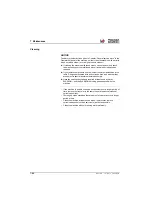
Application of anti-corrosive layer
Bear in mind the following instructions as you apply the anti-corrosive
protection:
• Carefully cover all fastening surfaces and components to which the
anti-corrosion protection may not be applied
– see chapter 7 " Components coated with anti-corrosive wax" on
page 7-84
• Apply ELASKON products with a brush or commercially available
spray equipment.
• The protective ELASKON coating can be removed with an ELASKON
cleanser if necessary.
• Spots are difficult to remove from clothing.
• Affix a “Wet paint!” or a similar sign to newly coated machines.
Treatment of oxidized surfaces
If in spite of all precautionary measures some components should be
affected by corrosion (oxidized), treat the oxidized area follows
Electric connections
• Remove the remaining protective wax at the oxidized area with an
ELASKON cleanser.
• Apply an oxide solvent (for example ELASKON Multi 80) to the
affected area.
• Treat the contact surfaces of the connection with for example
ELASKON Multi 80.
• Establish the connection.
• Apply/spray the anti-corrosion protection onto the electric connection
from all sides.
For sheet metal parts
• Remove the remaining protective wax at the oxidized area with an
ELASKON cleanser.
• Make all affected areas "blank", i.e. remove all remaining corrosion
and paint coating from the affected area down to the bare material.
otherwise the protective coating will not adhere properly.
• Clean the affected area with a cleaning solvent, and apply a 2-
component prime coating and then a 2-component paint coating to it.
• Then preserve the area with the anti-corrosion protection.
Summary of Contents for 418-12
Page 59: ...BA 418 12 1 0 418_12_3_Einleitung fm 3 27 Introduction 3 Right side of machine Fig 4 30 20 ...
Page 60: ...3 28 BA 418 12 1 0 418_12_3_Einleitung fm 3 Introduction Front of machine Fig 5 ...
Page 61: ...BA 418 12 1 0 418_12_3_Einleitung fm 3 29 Introduction 3 Rear of machine Fig 6 30 20 ...
Page 63: ...BA 418 12 1 0 418_12_3_Einleitung fm 3 31 Introduction 3 Outside right of the vehicle Fig 8 ...
Page 64: ...3 32 BA 418 12 1 0 418_12_3_Einleitung fm 3 Introduction Inside the cabin Fig 9 ...
Page 65: ...BA 418 12 1 0 418_12_3_Einleitung fm 3 33 Introduction 3 Engine compartment interior Fig 10 ...
Page 66: ...3 34 BA 418 12 1 0 418_12_3_Einleitung fm 3 Introduction Outside front of the vehicle Fig 11 ...
Page 67: ...BA 418 12 1 0 418_12_3_Einleitung fm 3 35 Introduction 3 Outside rear of the vehicle Fig 12 ...
Page 326: ...5 170 BA 418 12 1 0 418_12_5_Bedienung fm 5 Operation ...
Page 338: ...6 12 BA 418 12 1 0 418_12_6_Transport fm 6 Transport ...
Page 426: ...7 88 BA 418 12 1 0 418_12_7_Wartung fm 7 Maintenance ...
Page 462: ...8 36 BA 418 12 1 0 418_12_8_Betriebsstoerung fm 8 Malfunctions Notes ...
Page 499: ...BA 418 12 1 0 BA_418_12_V1_usSIX fm S 7 Index ...
Page 500: ...S 8 BA 418 12 1 0 BA_418_12_V1_usSIX fm Index ...
Page 527: ...FORM RTF 0907 Printed in U S A ...

