BA 418-12 * 1.0 * 418_12_8_Betriebsstoerung.fm
8-21
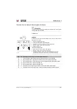
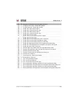
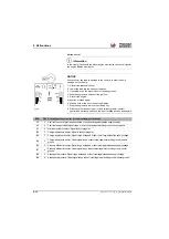
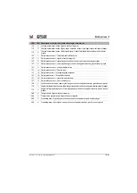
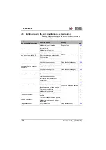
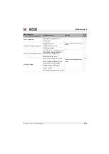
Malfunctions 8
516699
09
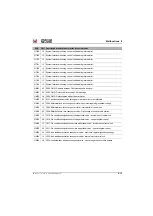
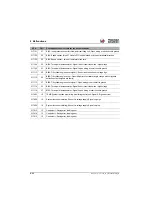
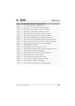
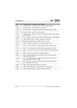
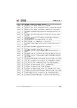
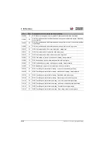
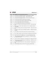
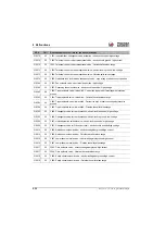
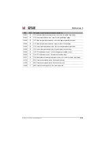
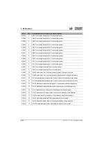
P006: OMD- control unit counter faulty
516699
15
P006: OMD- threshold slightly exceeded - Recalibration required
517005
09
B006: Sensor of the engine coolant temperature - timeout / abnormal clock rate
517005
19
B006: Sensor for the engine coolant temperature- Data reception with active error status
517008
02
B009: Driving functions, speed sensor - signal and CAN message data faulty or not plausible
517008
09
CCVS1 - B009: Driving functions, speed sensor, Can bus communication - timeout / abnormal
clock rate
517008
19
CCVS1 - B009: Driving functions, speed sensor, Can bus communication - data reception with
active error status
517009
09
B010: Operating mode, Can bus communication - timeout / abnormal clock rate
517009
19
B010: Operating mode, Can bus communication - data reception with active error status
517015
04
B016: Temperature sensor for fan controller - Short circuit to ground / low voltage
517015
12
B016: Temperature sensor for fan controller - Internal control unit error
517015
28
B016: Temperature sensor for fan controller - Open wiring or short circuit to positive
517027
03
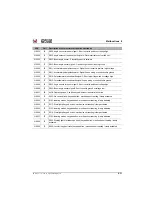
B028: Tilt cylinder angle sensor signal 2- Short circuit to positive or voltage high
517027
13
B028: angle sensor of the tilt cylinder, both signals - Data incorrect or not carried out
517027
27
B028: Tilt cylinder angle sensor signal 2- Short circuit to ground or voltage low
517056
09
B057: Sensor of the intake air temperature - timeout / abnormal clock rate
517056
19
B057: Sensor for the intake air temperature- Data reception with active error status
517101
03
B102: load pressure sensor for three-point rear lifting unit – short circuit to positive/high voltage
517101
12
B102: load pressure sensor for three-point rear lifting unit - Internal control unit error
517101
26
B102: load pressure sensor for three-point rear lifting unit - Parameterization outside of the valid
range
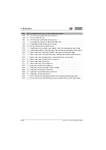
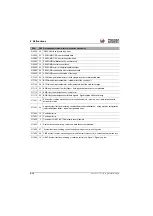
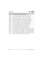
SPN
FMI
Description of severe errors for the drive electronics
Summary of Contents for 418-12
Page 59: ...BA 418 12 1 0 418_12_3_Einleitung fm 3 27 Introduction 3 Right side of machine Fig 4 30 20 ...
Page 60: ...3 28 BA 418 12 1 0 418_12_3_Einleitung fm 3 Introduction Front of machine Fig 5 ...
Page 61: ...BA 418 12 1 0 418_12_3_Einleitung fm 3 29 Introduction 3 Rear of machine Fig 6 30 20 ...
Page 63: ...BA 418 12 1 0 418_12_3_Einleitung fm 3 31 Introduction 3 Outside right of the vehicle Fig 8 ...
Page 64: ...3 32 BA 418 12 1 0 418_12_3_Einleitung fm 3 Introduction Inside the cabin Fig 9 ...
Page 65: ...BA 418 12 1 0 418_12_3_Einleitung fm 3 33 Introduction 3 Engine compartment interior Fig 10 ...
Page 66: ...3 34 BA 418 12 1 0 418_12_3_Einleitung fm 3 Introduction Outside front of the vehicle Fig 11 ...
Page 67: ...BA 418 12 1 0 418_12_3_Einleitung fm 3 35 Introduction 3 Outside rear of the vehicle Fig 12 ...
Page 326: ...5 170 BA 418 12 1 0 418_12_5_Bedienung fm 5 Operation ...
Page 338: ...6 12 BA 418 12 1 0 418_12_6_Transport fm 6 Transport ...
Page 426: ...7 88 BA 418 12 1 0 418_12_7_Wartung fm 7 Maintenance ...
Page 462: ...8 36 BA 418 12 1 0 418_12_8_Betriebsstoerung fm 8 Malfunctions Notes ...
Page 499: ...BA 418 12 1 0 BA_418_12_V1_usSIX fm S 7 Index ...
Page 500: ...S 8 BA 418 12 1 0 BA_418_12_V1_usSIX fm Index ...
Page 527: ...FORM RTF 0907 Printed in U S A ...

