BA 418-12 * 1.0 * 418_12_4_1_Inbetriebnahme.fm
4-27
Putting into operation 4
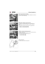
Hydraulic oil and coolant preheating (option)
The hydraulic oil preheating is used as a cold-starting aid at temperatures
below
−
5 °C (23 °F).
The hydraulic oil preheater reduces pollutant emissions during the warm-
up phase and saves fuel at the same time.
WARNING
Danger due to electric tension
Damaged cables and voltage sources can cause serious injury or death.
►
In Germany, cable
A
and the voltage source must be regularly
checked by an electrician according to the VDE 0701 standard.
►
Observe and follow the legal regulations of your country.
Information on putting into operation
Heating elements warm up the hydraulic oil in the hydraulic oil reservoir.
The hydraulic oil circuit can only be thoroughly warmed up if the
preheating is connected over a longer period of time.
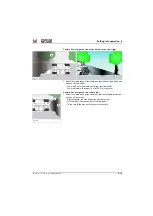
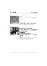
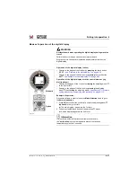
The vehicle plug receptacle
B
(230 V or 110 V) for the heater is located on
the bracket of the air filter.
The special cable
A
for the mains plug receptacle is included in the
standard package of the option.
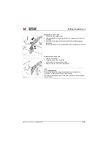
Start the preheating
1. Park the machine near a socket (230 or 110 V).
2. First connect the power cable
A
that is part of the standard package
with the vehicle plug receptacle
B
and then with the mains plug
receptacle
C
.
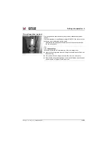
Switch off the preheating
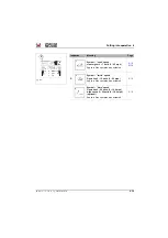
1. Before starting the diesel engine, first remove special cable
A
from the
mains outlet, then remove it from the machine outlet.
2. Close machine outlet
B
with a protective cap.
Fig. 144
A
Fig. 145
A
B
Summary of Contents for 418-12
Page 59: ...BA 418 12 1 0 418_12_3_Einleitung fm 3 27 Introduction 3 Right side of machine Fig 4 30 20 ...
Page 60: ...3 28 BA 418 12 1 0 418_12_3_Einleitung fm 3 Introduction Front of machine Fig 5 ...
Page 61: ...BA 418 12 1 0 418_12_3_Einleitung fm 3 29 Introduction 3 Rear of machine Fig 6 30 20 ...
Page 63: ...BA 418 12 1 0 418_12_3_Einleitung fm 3 31 Introduction 3 Outside right of the vehicle Fig 8 ...
Page 64: ...3 32 BA 418 12 1 0 418_12_3_Einleitung fm 3 Introduction Inside the cabin Fig 9 ...
Page 65: ...BA 418 12 1 0 418_12_3_Einleitung fm 3 33 Introduction 3 Engine compartment interior Fig 10 ...
Page 66: ...3 34 BA 418 12 1 0 418_12_3_Einleitung fm 3 Introduction Outside front of the vehicle Fig 11 ...
Page 67: ...BA 418 12 1 0 418_12_3_Einleitung fm 3 35 Introduction 3 Outside rear of the vehicle Fig 12 ...
Page 326: ...5 170 BA 418 12 1 0 418_12_5_Bedienung fm 5 Operation ...
Page 338: ...6 12 BA 418 12 1 0 418_12_6_Transport fm 6 Transport ...
Page 426: ...7 88 BA 418 12 1 0 418_12_7_Wartung fm 7 Maintenance ...
Page 462: ...8 36 BA 418 12 1 0 418_12_8_Betriebsstoerung fm 8 Malfunctions Notes ...
Page 499: ...BA 418 12 1 0 BA_418_12_V1_usSIX fm S 7 Index ...
Page 500: ...S 8 BA 418 12 1 0 BA_418_12_V1_usSIX fm Index ...
Page 527: ...FORM RTF 0907 Printed in U S A ...


