5-48
BA 418-12 * 1.0 * 418_12_5_Bedienung.fm
5 Operation
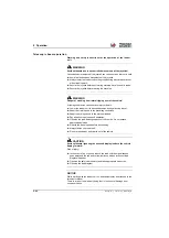
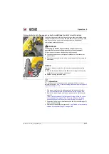
Overload control in fork-lift mode
In stacking mode, the overload control is active in the background and
only monitors the longitudinal stability of the telehandler.
WARNING
Risk of injury if the stability is ignored!
The safe load indicator does not warn:
- of lateral loads of the vehicle,
- a sudden overload of the telescopic boom,
- when driving in difficult terrain,
- as well as of influences from abrupt braking and deceleration!
Failure to observe stability can cause serious injury or death.
►
Only carry out transport trips with the loader unit lowered (transport
position).
►
Do not drive with raised or extended telescopic boom.
►
Do not turn on inclines.
►
Slow cornering.
►
Drive at walking speed
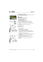
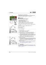
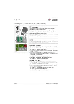
1. Press push button
➥
The LED in the touch button illuminates
➥
Symbol
appears in the display
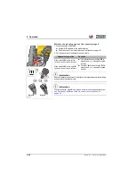
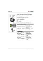
2. Lower the loader unit. To do this, press the joystick forward
C
➥
Nearly vertical lowering. This means that the telescopic boom is
automatically retracted when the loader unit is lowered (
f
).
➥
The loader unit lowering speed (
V
) is reduced depending on load
and angle. This means that in the upper range lowering speed is
slow, and in the lower range lowering speed is faster.
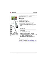
3. Raise the loader unit. To do this, pull the joystick backward
D
.
➥
Nearly vertical raising.
➥
Loader unit raising speed (
V
) is automatically reduced depending
on load and angle. This means that in the lower range raising speed
is faster, and in the upper range raising speed is slower.
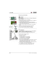
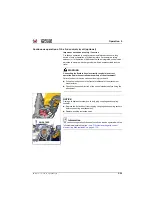
4. Carefully extend the telescopic boom. To do this, press the roller
forward in the joystick.
➥
Observe the display unit (overload warning device) and then act
see "Working with the pallet fork" on page 5-95
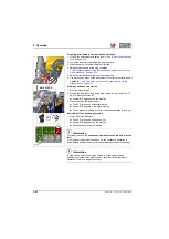
Information
The overload control can be bridged briefly for positioning heavy loads
with precision (two-hand operation)
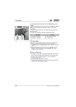
– see "Overload limitation in manual
!
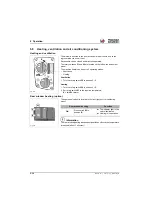
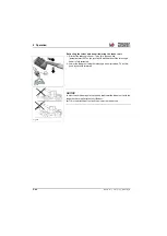
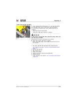
Fig. 230
Vmax
f
v
v
v
d
D
C
2
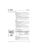
Fig. 231
Vmin
Vmax
D
V
V
V
D
Summary of Contents for 418-12
Page 59: ...BA 418 12 1 0 418_12_3_Einleitung fm 3 27 Introduction 3 Right side of machine Fig 4 30 20 ...
Page 60: ...3 28 BA 418 12 1 0 418_12_3_Einleitung fm 3 Introduction Front of machine Fig 5 ...
Page 61: ...BA 418 12 1 0 418_12_3_Einleitung fm 3 29 Introduction 3 Rear of machine Fig 6 30 20 ...
Page 63: ...BA 418 12 1 0 418_12_3_Einleitung fm 3 31 Introduction 3 Outside right of the vehicle Fig 8 ...
Page 64: ...3 32 BA 418 12 1 0 418_12_3_Einleitung fm 3 Introduction Inside the cabin Fig 9 ...
Page 65: ...BA 418 12 1 0 418_12_3_Einleitung fm 3 33 Introduction 3 Engine compartment interior Fig 10 ...
Page 66: ...3 34 BA 418 12 1 0 418_12_3_Einleitung fm 3 Introduction Outside front of the vehicle Fig 11 ...
Page 67: ...BA 418 12 1 0 418_12_3_Einleitung fm 3 35 Introduction 3 Outside rear of the vehicle Fig 12 ...
Page 326: ...5 170 BA 418 12 1 0 418_12_5_Bedienung fm 5 Operation ...
Page 338: ...6 12 BA 418 12 1 0 418_12_6_Transport fm 6 Transport ...
Page 426: ...7 88 BA 418 12 1 0 418_12_7_Wartung fm 7 Maintenance ...
Page 462: ...8 36 BA 418 12 1 0 418_12_8_Betriebsstoerung fm 8 Malfunctions Notes ...
Page 499: ...BA 418 12 1 0 BA_418_12_V1_usSIX fm S 7 Index ...
Page 500: ...S 8 BA 418 12 1 0 BA_418_12_V1_usSIX fm Index ...
Page 527: ...FORM RTF 0907 Printed in U S A ...

