BA 418-12 * 1.0 * 418_12_5_Bedienung.fm
5-63
Operation 5
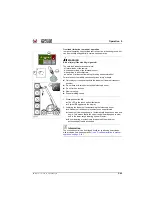
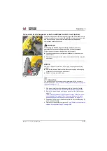
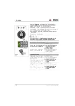
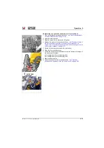
14-pole front socket (option)
This option is only possible in connection with a SKID STEER quickhitch
facility.
Three power circuits for activating electro-hydraulic control valves, and an
additional 4th power circuit for switching electrical functions can be
operated with the 14-pole front plug receptacle
C
.
It can be queried in the digital display what control circuit is activated. To
do this, briefly press button
in the digital display.
➥
The symbol
Q/1, 2, 3 or 4
appears for a few seconds and shows the
active control circuit.
Information
The first 3 electrical circuits can only be operated separately, indicated by
the corresponding symbols
in the digital display.
The 4th electrical circuit can be operated in addition to the other three
electrical circuits.
The control circuits are only ready for operation with activated work
hydraulics for safety reasons
– see chapter 4 " Secure the control lever
(joystick)/lock the work hydraulics" on page 4-56
.
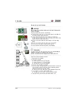
• The selection and activation of the 3 electrical circuits occurs via the
• The selected electrical circuit (1, 2 or 3) is operated with the rocker
switch
on the joystick.
• The 4th electrical circuit is operated with push button
joystick.
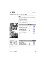
• The operation of the individual electrical circuits
14-pole plug receptacle" on page 5-64
B
A
1
2
3
4
Fig. 246
C
SKID STEER
Summary of Contents for 418-12
Page 59: ...BA 418 12 1 0 418_12_3_Einleitung fm 3 27 Introduction 3 Right side of machine Fig 4 30 20 ...
Page 60: ...3 28 BA 418 12 1 0 418_12_3_Einleitung fm 3 Introduction Front of machine Fig 5 ...
Page 61: ...BA 418 12 1 0 418_12_3_Einleitung fm 3 29 Introduction 3 Rear of machine Fig 6 30 20 ...
Page 63: ...BA 418 12 1 0 418_12_3_Einleitung fm 3 31 Introduction 3 Outside right of the vehicle Fig 8 ...
Page 64: ...3 32 BA 418 12 1 0 418_12_3_Einleitung fm 3 Introduction Inside the cabin Fig 9 ...
Page 65: ...BA 418 12 1 0 418_12_3_Einleitung fm 3 33 Introduction 3 Engine compartment interior Fig 10 ...
Page 66: ...3 34 BA 418 12 1 0 418_12_3_Einleitung fm 3 Introduction Outside front of the vehicle Fig 11 ...
Page 67: ...BA 418 12 1 0 418_12_3_Einleitung fm 3 35 Introduction 3 Outside rear of the vehicle Fig 12 ...
Page 326: ...5 170 BA 418 12 1 0 418_12_5_Bedienung fm 5 Operation ...
Page 338: ...6 12 BA 418 12 1 0 418_12_6_Transport fm 6 Transport ...
Page 426: ...7 88 BA 418 12 1 0 418_12_7_Wartung fm 7 Maintenance ...
Page 462: ...8 36 BA 418 12 1 0 418_12_8_Betriebsstoerung fm 8 Malfunctions Notes ...
Page 499: ...BA 418 12 1 0 BA_418_12_V1_usSIX fm S 7 Index ...
Page 500: ...S 8 BA 418 12 1 0 BA_418_12_V1_usSIX fm Index ...
Page 527: ...FORM RTF 0907 Printed in U S A ...

