5-128
BA 418-12 * 1.0 * 418_12_5_Bedienung.fm
5 Operation
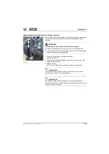
Balltrailer coupling (option)
The ball hitch coupling is used for tractor vehicles and self-propelled work
machines according to § 43 clause 4 of the StVZO (German road traffic
regulations) in the Federal Republic of Germany.
WARNING
Accident hazard due to a damaged trailer coupling!
Failure to observe this can cause serious injury or death.
►
Check the ball hitch for damage before using it.
►
Ensure a minimum diameter of 49.5 mm at any point of the ball.
►
Have a damaged or malfunctioning ball hitch immediately repaired or
replaced by an authorized service center.
• Only trailers may be towed that are equipped with ball traction
couplings. Any other use is prohibited
• Do not hitch trailers with positive steering.
• Follow the regulations of the employer’s liability insurance associations
of your country when coupling or uncoupling a trailer.
•
Note the trailer and support loads:
See the notice sign fixed near the
ball hitch or in this operator's manual
• Keep the ball clean and apply a thin coat of grease. However, do not
apply any grease to the ball when using a stabilization system, such as
Westphalia “SSK”.
• Check all fastening screws of the towing gear regularly or have them
retightened by an authorized service center to the specified tightening
torque.
Information
In the Federal Republic of Germany, only approved ball hitches with an
EC approval or EC certification logo may be used.
Refer to and follow
the General Certification for Vehicles (Germany) or the Data
Confirmation (Germany) for information on other requirements!
Get informed on and follow the legal regulations of your country.
Information
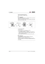
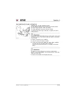
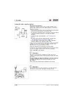
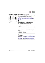
The height-adjustable ball hitch can be completely removed if necessary.
To do this: unlock the ball hitch with lever
A
and remove it from the
adjustment plate with an upward movement.
Fig. 320
A
Summary of Contents for 418-12
Page 59: ...BA 418 12 1 0 418_12_3_Einleitung fm 3 27 Introduction 3 Right side of machine Fig 4 30 20 ...
Page 60: ...3 28 BA 418 12 1 0 418_12_3_Einleitung fm 3 Introduction Front of machine Fig 5 ...
Page 61: ...BA 418 12 1 0 418_12_3_Einleitung fm 3 29 Introduction 3 Rear of machine Fig 6 30 20 ...
Page 63: ...BA 418 12 1 0 418_12_3_Einleitung fm 3 31 Introduction 3 Outside right of the vehicle Fig 8 ...
Page 64: ...3 32 BA 418 12 1 0 418_12_3_Einleitung fm 3 Introduction Inside the cabin Fig 9 ...
Page 65: ...BA 418 12 1 0 418_12_3_Einleitung fm 3 33 Introduction 3 Engine compartment interior Fig 10 ...
Page 66: ...3 34 BA 418 12 1 0 418_12_3_Einleitung fm 3 Introduction Outside front of the vehicle Fig 11 ...
Page 67: ...BA 418 12 1 0 418_12_3_Einleitung fm 3 35 Introduction 3 Outside rear of the vehicle Fig 12 ...
Page 326: ...5 170 BA 418 12 1 0 418_12_5_Bedienung fm 5 Operation ...
Page 338: ...6 12 BA 418 12 1 0 418_12_6_Transport fm 6 Transport ...
Page 426: ...7 88 BA 418 12 1 0 418_12_7_Wartung fm 7 Maintenance ...
Page 462: ...8 36 BA 418 12 1 0 418_12_8_Betriebsstoerung fm 8 Malfunctions Notes ...
Page 499: ...BA 418 12 1 0 BA_418_12_V1_usSIX fm S 7 Index ...
Page 500: ...S 8 BA 418 12 1 0 BA_418_12_V1_usSIX fm Index ...
Page 527: ...FORM RTF 0907 Printed in U S A ...

