5-138
BA 418-12 * 1.0 * 418_12_5_Bedienung.fm
5 Operation
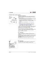
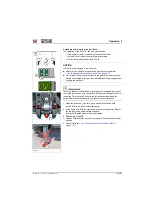
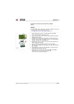
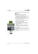
Additional rear hydraulic control circuit (double-action, option)
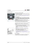
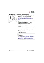
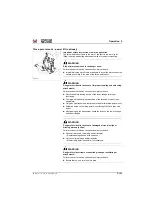
Flat connector plugs: rear auxiliary control circuits
Flat connector plugs are installed on the rear of the machine for operating
hydraulic attachments with additional hydraulic functions
E
.
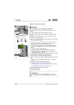
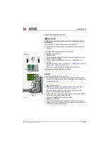
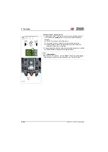
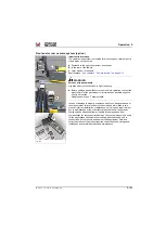
Attachment and operation of the flat connector plugs in the rear
– see "Connect attachment to the rear flat connector plugs" on
page 5-139
and
“Operation of the flat connector plugs in the rear” on
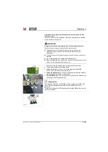
WARNING
Connecting the flexible lines incorrectly results in incorrect
operation and/or uncontrolled movements of the attachment!
Failure to observe this can cause serious injury or death.
►
Note the operator's manual of the attachment manufacturer and act
accordingly!
►
Check the response direction of the control elements before using the
attachment.
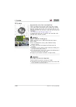
NOTICE
Damage to hydraulic system due to dirty plug couplings and coupling
sockets!
►
Remove the dirt and dust from the flat connector plugs before
connecting the attachment!
►
Replace missing protective caps.
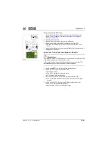
Information
The hydraulically activated auxiliary control circuit can also be operated
with the “oil volume setting“ option
– see "Oil volume setting with control
element (jog dial) (optional)" on page 5-112
Refer to the specifications for the possible oil volumes
consumer pressure at the hydraulic flat connector plugs" on page 9-6
Fig. 330
E
Summary of Contents for 418-12
Page 59: ...BA 418 12 1 0 418_12_3_Einleitung fm 3 27 Introduction 3 Right side of machine Fig 4 30 20 ...
Page 60: ...3 28 BA 418 12 1 0 418_12_3_Einleitung fm 3 Introduction Front of machine Fig 5 ...
Page 61: ...BA 418 12 1 0 418_12_3_Einleitung fm 3 29 Introduction 3 Rear of machine Fig 6 30 20 ...
Page 63: ...BA 418 12 1 0 418_12_3_Einleitung fm 3 31 Introduction 3 Outside right of the vehicle Fig 8 ...
Page 64: ...3 32 BA 418 12 1 0 418_12_3_Einleitung fm 3 Introduction Inside the cabin Fig 9 ...
Page 65: ...BA 418 12 1 0 418_12_3_Einleitung fm 3 33 Introduction 3 Engine compartment interior Fig 10 ...
Page 66: ...3 34 BA 418 12 1 0 418_12_3_Einleitung fm 3 Introduction Outside front of the vehicle Fig 11 ...
Page 67: ...BA 418 12 1 0 418_12_3_Einleitung fm 3 35 Introduction 3 Outside rear of the vehicle Fig 12 ...
Page 326: ...5 170 BA 418 12 1 0 418_12_5_Bedienung fm 5 Operation ...
Page 338: ...6 12 BA 418 12 1 0 418_12_6_Transport fm 6 Transport ...
Page 426: ...7 88 BA 418 12 1 0 418_12_7_Wartung fm 7 Maintenance ...
Page 462: ...8 36 BA 418 12 1 0 418_12_8_Betriebsstoerung fm 8 Malfunctions Notes ...
Page 499: ...BA 418 12 1 0 BA_418_12_V1_usSIX fm S 7 Index ...
Page 500: ...S 8 BA 418 12 1 0 BA_418_12_V1_usSIX fm Index ...
Page 527: ...FORM RTF 0907 Printed in U S A ...

