BA 418-12 * 1.0 * 418_12_3_Einleitung.fm
3-5
Introduction 3
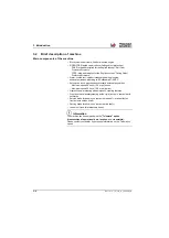
Hydrostatic drive with inching
The diesel engine permanently drives a hydraulic pump (variable
displacement pump), the oil flow of which is sent to a hydraulic motor
flanged on the transfer gearbox. The output of the hydraulic motor is
passed on via the transfer case (flanged to the front axle) further via the
universal joint shaft connection to the rear axle so that a permanent all-
wheel drive exists.
Work hydraulics and 4 wheel steering
A gear pump (flanged on the variable displacement pump of the drive)
supplies the work hydraulics and, via a priority valve, also the hydrostatic
steering.
The oil flow of the pump depends on the diesel engine speed.
When the machine is in operation, the entire diesel engine output can be
transmitted to the gear pump for the work hydraulics and steering. This is
made possible by a so-called inching valve that responds as soon as the
brake/inching pedal is used, reducing or cutting off power input of the
drive.
Therefore, engine output is fully available for the loader unit by pressing
the accelerator pedal and the brake/inching pedal at the same time.
Cooling system
There is a combined water-hydraulic oil cooler, intercooler and fuel cooler
in the engine compartment.
The hydraulic oil temperature as well as the cooling temperature of the
diesel engine are indicated via the control lamps in the display instrument
(dashboard).
Summary of Contents for 418-12
Page 59: ...BA 418 12 1 0 418_12_3_Einleitung fm 3 27 Introduction 3 Right side of machine Fig 4 30 20 ...
Page 60: ...3 28 BA 418 12 1 0 418_12_3_Einleitung fm 3 Introduction Front of machine Fig 5 ...
Page 61: ...BA 418 12 1 0 418_12_3_Einleitung fm 3 29 Introduction 3 Rear of machine Fig 6 30 20 ...
Page 63: ...BA 418 12 1 0 418_12_3_Einleitung fm 3 31 Introduction 3 Outside right of the vehicle Fig 8 ...
Page 64: ...3 32 BA 418 12 1 0 418_12_3_Einleitung fm 3 Introduction Inside the cabin Fig 9 ...
Page 65: ...BA 418 12 1 0 418_12_3_Einleitung fm 3 33 Introduction 3 Engine compartment interior Fig 10 ...
Page 66: ...3 34 BA 418 12 1 0 418_12_3_Einleitung fm 3 Introduction Outside front of the vehicle Fig 11 ...
Page 67: ...BA 418 12 1 0 418_12_3_Einleitung fm 3 35 Introduction 3 Outside rear of the vehicle Fig 12 ...
Page 326: ...5 170 BA 418 12 1 0 418_12_5_Bedienung fm 5 Operation ...
Page 338: ...6 12 BA 418 12 1 0 418_12_6_Transport fm 6 Transport ...
Page 426: ...7 88 BA 418 12 1 0 418_12_7_Wartung fm 7 Maintenance ...
Page 462: ...8 36 BA 418 12 1 0 418_12_8_Betriebsstoerung fm 8 Malfunctions Notes ...
Page 499: ...BA 418 12 1 0 BA_418_12_V1_usSIX fm S 7 Index ...
Page 500: ...S 8 BA 418 12 1 0 BA_418_12_V1_usSIX fm Index ...
Page 527: ...FORM RTF 0907 Printed in U S A ...

