9-10
BA 418-12 * 1.0 * 418_12_9_Technische_Daten.fm
9 Technical data
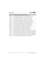
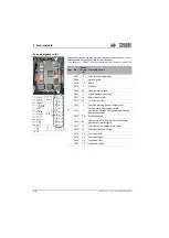
Fuse assignment (C)
The plug console with the fuses is located under the switch console on the
right on the instrument panel
– see chapter 7 " Relays, fuses on the
printed circuit board" on page 7-66
.
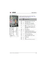
Relay on the printed circuit board
The printed circuit board with the relays (shown from above) is located
under the cover on the switch console on the right on the instrument panel
– see chapter 7 " Relays, fuses on the printed circuit board" on page 7-66
Fig. 438
F086
F087
F088
F089
F090
F091
Item No.
Rated
current
(A)
Protected circuit
C
F086
10
Input voltage of cabin controller
F087
10
F088
10
F089
10
F090
10
F091
10
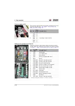
Fig. 439
1
2
3
4
5
13
6
7
8
9
10
11
12
Item
Switching
relays
1
1.
The switch relay designation in the parenthesis (..) refers to the circuit diagram
Protected circuit
1
K058
Not assigned
2
K010
Turn indicator relay
3
K025
Relay interval
4
K023
Relay for windshield wiper level 1
5
B018
Buzzer
6
K306 (K101)
Relay of 7-pole plug receptacle
7
K305 (K016)
Relay of 7-pole plug receptacle
8
K304 (K033)
Relay of windshield heating
9
K303 (K049)
Relay of work light on telescopic boom
10
K302 (K047)
Relay of rear work light for cabin
11
K301 (K048)
Relay of front work light for cabin
12
K312
Not assigned
13
K311 (K030)
Brake relay
14
K310 (K114)
Rotating beacon relay
15
K309 (K003)
Backup warning system relay
16
K308
No function
17
K307 (K102)
Relay of 7-pole plug receptacle
Summary of Contents for 418-12
Page 59: ...BA 418 12 1 0 418_12_3_Einleitung fm 3 27 Introduction 3 Right side of machine Fig 4 30 20 ...
Page 60: ...3 28 BA 418 12 1 0 418_12_3_Einleitung fm 3 Introduction Front of machine Fig 5 ...
Page 61: ...BA 418 12 1 0 418_12_3_Einleitung fm 3 29 Introduction 3 Rear of machine Fig 6 30 20 ...
Page 63: ...BA 418 12 1 0 418_12_3_Einleitung fm 3 31 Introduction 3 Outside right of the vehicle Fig 8 ...
Page 64: ...3 32 BA 418 12 1 0 418_12_3_Einleitung fm 3 Introduction Inside the cabin Fig 9 ...
Page 65: ...BA 418 12 1 0 418_12_3_Einleitung fm 3 33 Introduction 3 Engine compartment interior Fig 10 ...
Page 66: ...3 34 BA 418 12 1 0 418_12_3_Einleitung fm 3 Introduction Outside front of the vehicle Fig 11 ...
Page 67: ...BA 418 12 1 0 418_12_3_Einleitung fm 3 35 Introduction 3 Outside rear of the vehicle Fig 12 ...
Page 326: ...5 170 BA 418 12 1 0 418_12_5_Bedienung fm 5 Operation ...
Page 338: ...6 12 BA 418 12 1 0 418_12_6_Transport fm 6 Transport ...
Page 426: ...7 88 BA 418 12 1 0 418_12_7_Wartung fm 7 Maintenance ...
Page 462: ...8 36 BA 418 12 1 0 418_12_8_Betriebsstoerung fm 8 Malfunctions Notes ...
Page 499: ...BA 418 12 1 0 BA_418_12_V1_usSIX fm S 7 Index ...
Page 500: ...S 8 BA 418 12 1 0 BA_418_12_V1_usSIX fm Index ...
Page 527: ...FORM RTF 0907 Printed in U S A ...

