10
10/25/2016 - DOCUMENT NUMBER: 10-2500
© 2016 AEM Performance Electronics
AQ-1 DATA LOGGER
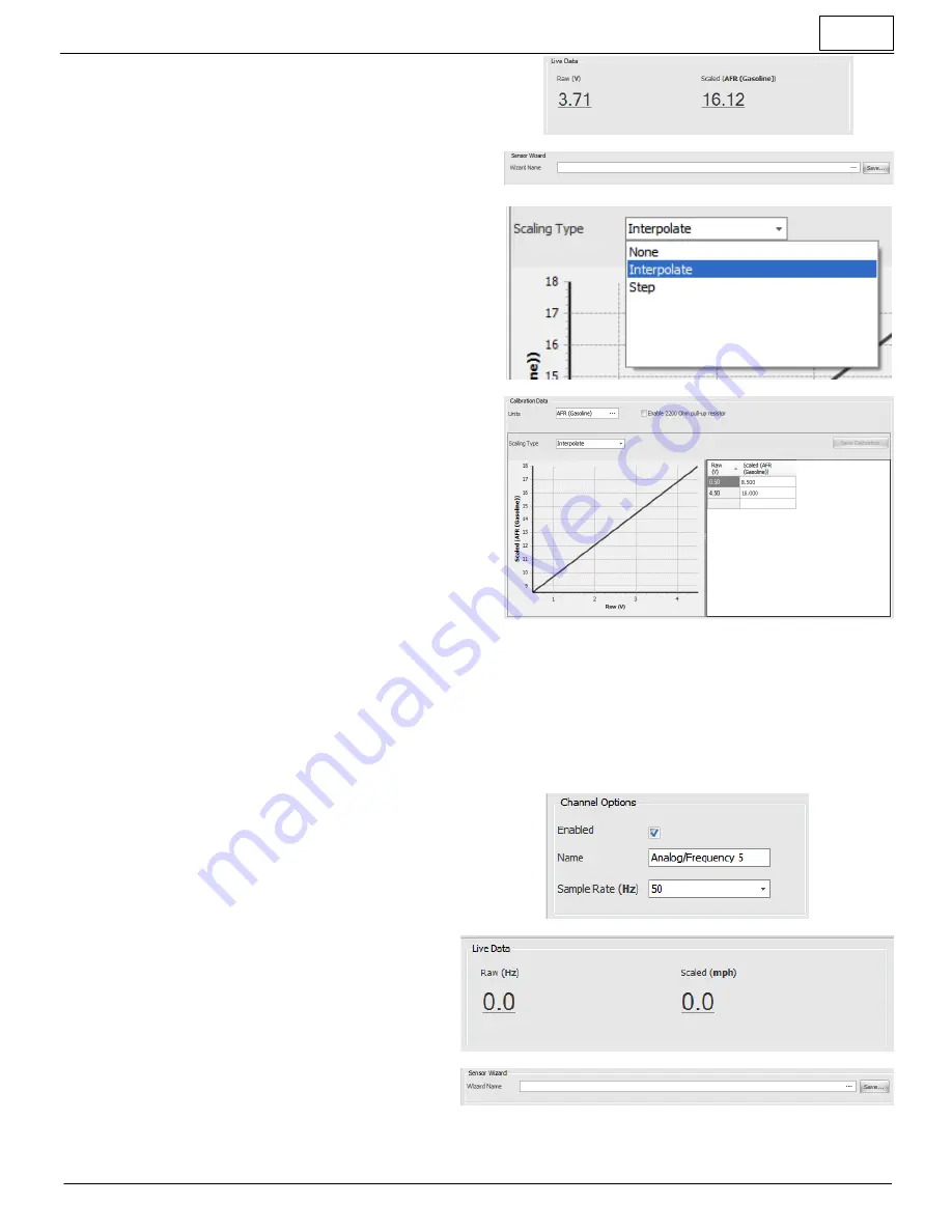
Live Data
·
Displays the raw voltage measured at the input pin
·
Displays the scaled value as will be recorded in the log
·
AQ-1 requires 12V power at main connector for proper
readings
Sensor Wizard
·
Load known sensor calibrations from Wizard database
·
Save custom sensor calibrations to Wizard database
Scaling Type
·
Scaling type is typically set to
Interpolate
.
Step
can be
used for gear position sensors as an example
Calibration Data
·
View/create sensor calibrations
·
View/set the units of the scaled value to be recorded in the
data log
·
View/set the calibration points/curve
·
The 2200 Ohm pull-up resistor is typically enabled for two-
wire RTD type sensors, unless that sensor is already
connected to another logger/ECU device
Configuration: Analog / Frequency Inputs 5 - 8
The second four analog/frequency inputs are designed to accept and sample a 0-5V signal or a 0-16V signal at up to
1000Hz. In addition, frequency and duty cycle type signals may be logged. This signal may be scaled to engineering
units and recorded in the data log for post-analysis. There is no software configurable pull-up resistor available on this
input type.
Please reference
Configuration: Analog Inputs 1-4
Channel Options
·
Enabled checkbox determines if channel is logged or
not
·
Set the name that will appear in the data log
·
Set the sampling rate of this input
·
Frequency mode sampling is
Live Data
·
Displays the raw voltage measured at the input pin
·
Displays the scaled value as will be recorded in the
log
·
AQ-1 requires 12V power at main connector for
proper readings
Sensor Wizard
·
Load known sensor calibrations from Wizard
database
·
Save custom sensor calibrations to Wizard database


