background image

9

10/25/2016 -  DOCUMENT NUMBER: 10-2500

© 2016 AEM Performance Electronics

AQ-1 DATA LOGGER

·

All Analog, Digital, Frequency channels may be used
as logging conditions

·

Only Engine RPM and Vehicle Speed are available
from GPS, AEMnet, or OBD-II

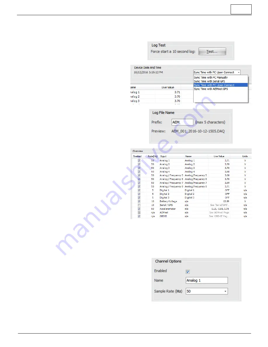
Log Test

·

Temporarily forces the logger to  begin  logging  and
terminate after 10 seconds

·

Useful for testing logger configuration

Device Date And Time

·

Log files will be time stamped using this date/time

·

AQ-1 date/time setting will reset if  permanent  12V
power is removed

·

Select method by which AQ-1 date/time should be
synced

Log File Name

·

Log files will be named using the configurable prefix,
file count, and date/time

Input Overview

·

Provides an overview of which channels are  enabled
for logging and other settings

·

Enabled flag, logging rate, and name can be set for
most channels

·

Live  channel  reading  can  be  viewed  for  most
channels.  Note: Permanent 12V must be present on
main connector for proper operation

Configuration: Analog Inputs 1 - 4

The first four analog inputs are designed to accept and sample a 0-5V signal at up to 1000Hz.  This signal may be scaled
to engineering units and recorded in the data log for post-analysis.  A software configurable pull-up resistor is provided for
two-wire RTD sensors or similar.

Channel Options

·

Enabled checkbox determines if channel is logged or not

·

Set the name that will appear in the data log

·

Set the sampling rate of this input

Summary of Contents for AQ-1

Page 1: ...ng and Motorsports because it installs easily can read live parameters from ancillary sensors AEMnet enabled devices GPS and more and put them into a single log make your data easy to view Whether you race a late model EFI equipped OR carbureted vehicle the AQ 1 is the ideal solution for your data acquisition needs Features Four 4 0 5VDC Analog Inputs with software selectable 2 2k pull up resistor...

Page 2: ...own harness The connector part numbers AEM does not supply these parts separately outside the 30 2906 96 or 30 2907 96 are provided below for this purpose Manufacturer Part Number Description Delphi 12110487 36 Way Black Micro Pack 100W Sealed Female Connector Max Current 7 5 amps Delphi 12110490 LOCK STRAIN RLF MIC P 100W RH GRA Delphi 12110488 LOCK RETAINER CONN 36 CLR Delphi 12110489 Green Mult...

Page 3: ...5 16V Max Frequency signals must be clean DC square wave only 13 Analog Frequency Input 6 16V Max Frequency signals must be clean DC square wave only 14 Analog Frequency Input 7 16V Max Frequency signals must be clean DC square wave only 15 Analog Frequency Input 8 16V Max Frequency signals must be clean DC square wave only 16 RS 232 Serial Tx AEMEMS Series 1 2 or NMEA0183 GPS Only 17 RS 232 Seria...

Page 4: ... your engine management system or ECU No you don t need a pull up resistor when You want to log an AIT sensor that you purchased from a third party like AEM and installed in your intake and is not connected to any other ECU EMS logger Wiring Analog Frequency Input 4 8 This class of inputs is suitable for logging the output from a variety of sensors which have a continuously variable analog output ...

Page 5: ...ttery voltage and the 2 second wire is connected to a low side output of an ECU or controller or ground wire 2 should be connected to this input for the purposes of logging A start stop switch typically has two terminals where 1 is to be connected to the logger and 2 is connected to ground Important Note These inputs are not intended for use with solenoids or signal sources that are pulsed with a ...

Page 6: ... equipped with a non configurable 120 Ohm resistor The following Deutsch DTM4 pin termination plugs are available from your AEMdealer PN Description 35 3440 F AEMNET TERMINATION PLUG FEMALE 35 3440 M AEMNET TERMINATION PLUG MALE Configuration Software Overview The AEM AQ 1 Data Logger is configured using PC software available for download at www aemelectronics com Once downloaded and installed con...

Page 7: ... desired input feature to navigate to its configuration page Center Pane All configurable options or live readings from the device will be displayed in this area Some information or options are only available when connected through USB to an AQ 1 that is powered by a 12V system through the main connector Device Information When connected to an AQ 1 via USB this area will display information about ...

Page 8: ...figuration Open configuration from PC and edit offline Save Configuration Save currently opened configuration to PC with same filename Save Configuration As Save currently opened configuration to PC with different filename New Configuration Create a new configuration offline and begin editing Configuration Input Channel Overview Logging Conditions This page provides some important interfaces for c...

Page 9: ...g the configurable prefix file count and date time Input Overview Provides an overview of which channels are enabled for logging and other settings Enabled flag logging rate and name can be set for most channels Live channel reading can be viewed for most channels Note Permanent 12V must be present on main connector for proper operation Configuration Analog Inputs 1 4 The first four analog inputs ...

Page 10: ... connected to another logger ECU device Configuration Analog Frequency Inputs 5 8 The second four analog frequency inputs are designed to accept and sample a 0 5V signal or a 0 16V signal at up to 1000Hz In addition frequency and duty cycle type signals may be logged This signal may be scaled to engineering units and recorded in the data log for post analysis There is no software configurable pull...

Page 11: ...e period of the sampled signal in milliseconds no other scaling options are provided Input Mode Duty Cycle Records the duty cycle in percentage of the incoming signal such as may be typical on a fuel injector The AQ 1 accommodates a typical 12V port injection fuel injector is without additional input circuitry conditioning Duty cycle percentage may be based off the high or low pulse of the signal ...

Page 12: ...e amount of time configured by Beacon Obscuring Time Calibration Data View create sensor calibrations Scaling type is typically set to Interpolate Step can be used for gear position sensors as an example View set the units of the scaled value to be recorded in the data log View set the calibration points curve The 2200 Ohm pull up resistor is typically enabled for two wire RTD type sensors unless ...

Page 13: ...Pin 1 Switched 12V Channel Options Enabled checkbox determines if channel is logged or not The channel name is fixed at Battery Voltage Set the sampling rate of this input Live Data Displays the voltage level measured at the input pin Configuration Accelerometer The internal 3 axis accelerometer 4g requires a simple calibration procedure prior to use Channel Options Enabled checkbox determines if ...

Page 14: ... of an AEM Series I or Series II EMS Channel Options Enabled checkbox determines if channel is logged or not Set the sampling rate of this input Refer to your GPS or EMS user manual to determine the appropriate baud rate setting Select GPS or AEM EMS input mode Sensor Wizard Load known sensor calibrations from Wizard database Save custom sensor calibrations to Wizard database Live Data GPS GPS dat...

Page 15: ...ed by clicking the unit hyperlinks Configuration AEMnet The AEMnet input provides Plug and Play functionality and allows logging for AEMnet devices AEMnet Devices Auto Discover Connect the AEMnet devices to the AQ 1 and ensure all devices are powered then click Auto Discover to configure the AQ 1 to log the connected devices Add Remove Device As an alternative to performing an Auto Discover right ...

Page 16: ... conditions experienced while operating a vehicle and logging This information will be stored in the data log and available for review in AEMdata by selecting the menu option View Notes Configuration Sensor Wizard The Sensor Wizard is available on the majority of the input configuration pages to assist in configuration It is essentially a database of sensor calibrations that AEM has compiled and m...

Page 17: ...l remain locked in place If any logs are present on the SD card they will automatically be downloaded when the AQ 1 configuration software detects the logger through its USB connection The following dialog will automatically open and download convert and copy the log file to the specified folder The files then may be optionally opened in AEMdata for analysis Please note that the files as recorded ...

Page 18: ...uire re formatting This can be accomplished by inserting the SD card into the AQ 1 connecting the AQ 1 to a PC via the USB cable and using Windows Explorer to format the drive FAT or FAT16 is the recommended file system for the fastest performance however FAT32 is supported Device Information The device information pane displays information about the connected AQ 1 the currently configured data ra...

Page 19: ...s set incorrectly FAQ Troubleshooting I just tried to download some logs and it says there are files with errors This is caused be either a Permanent 12V must be connected to Pin 6 and Switched 12V must be connected to Pin 1 Permanent 12V must remain constant to allow the logger to properly finish writing to the file after Switched 12V is removed or b Logging conditions should be selected such tha...

Page 20: ...uel Pressure Gauge 0 to 15psi SAE Only Analog 1 8 AEMnet 30 0310 X Series Inline Wideband UEGO AFR Controller LSU4 9 Analog 1 8 AEMnet 30 0313 X Series GPS Speedometer Gauge 0 to 160mph 0 to 260kph Analog 1 8 AEMnet 30 2203 Vehicle Dynamics Module Analog 1 8 AEMnet 30 2340 4 Channel Wideband UEGO AFR Controller Analog 1 8 AEMnet 30 49xx Wideband Failsafe Wideband Flex Fuel Failsafe Analog 1 8 AEMn...

Page 21: ...horized repairs or alterations voids this w arranty AEM disclaims any liability for consequential damages due to breach of any w ritten or implied w arranty on all products manufactured by AEM Warranty returns w ill only be accepted by AEM w hen accompanied by a valid Return Merchandise Authorization RMA number Product must be received by AEM w ithin 30 days of the date the RMA is issued UEGO oxyg...

Page 22: ...s AQ 1 DATA LOGGER Specifications Dimensions width 4 55 122 in mm length 4 8 116 in mm height 1 44 37 in mm mass 8 226 oz g Supply Voltage min 7 VDC max 18 VDC Supply Current 13 8V nominal 150 0 mA Operating Temperature min 4 20 degF degC max 16V Supply 185 85 degF degC ...

Reviews: